
Note. Before installing the camshafts, they should be carefully inspected, and before removing each of the shafts, its axial clearance should be checked (see item 13).
Removing
1. Disconnect the ground wire from the battery (see paragraph 1 of chapter 5).
2. Remove the cylinder head cover (see paragraph 4).
3. Bring the #1 piston to TDC on the compression stroke (see paragraph 3). Visually verify that the engine is at TDC on the compression stroke - the alignment mark on the crankshaft pulley/damper is aligned with the mark «0» on the timing chain cover, and the TDC marks on the camshaft sprockets are aligned and parallel to the upper edge of the timing chain cover (rice. 3.8 and 6.8)
4. After aligning the TDC marks, make paint marks on the timing chain links at the point of their mating with the upper alignment marks on the timing gear sprockets (pic. 7.4).
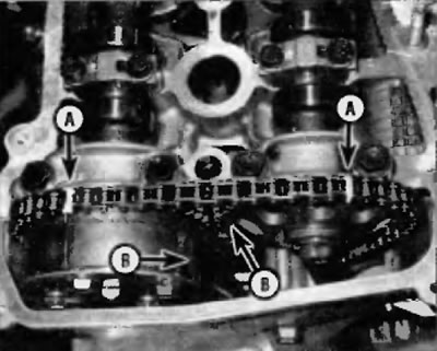
Pic. 7.4. With the TDC marks aligned, mark with paint the timing chain links at the points of their mating with the upper alignment marks on the camshaft sprockets (A). Two other labels (IN) used to align the sprockets with the timing chain during installation
Note. There are two sets of marks on the camshaft sprockets. The marks that align at TDC are only reference marks for the TDC position and nothing more: two other marks are used to align the sprockets with the timing chain during installation.
5. Remove the timing chain tensioner from the chain cover (pic. 6.14, a, b) and camshaft position sensor from the cylinder head (see chapter 6).
6. Hold the camshaft from rotation by the hex section with a large wrench and loosen the exhaust camshaft sprocket bolts a few turns. If the camshaft sprockets turn while releasing the bolts, turn the engine clockwise until the marks «TDC» on the sprockets of the shafts were again combined.
Note. If the intake camshaft sprocket needs to be removed (with actuator WT), follow the procedure and remove the sprocket mounting bolts later on a workbench.
7. Turn out a bolt of fastening of an asterisk of a final camshaft. Loosen the exhaust camshaft bearing cap bolts in two or three stages, starting at the outer caps and moving towards the center (in reverse order of tightening). Turn out bolts of covers and remove a shaft from a head of cylinders. Unhook the chain from the sprocket and remove the sprocket from the engine.
8. Check up markings on covers of bearings of an inlet camshaft. They must be marked with numbers from 1 to 5 «I» (what does intake mean» (Inlet), which indicates that the covers are for the intake camshaft (pic. 7.8).
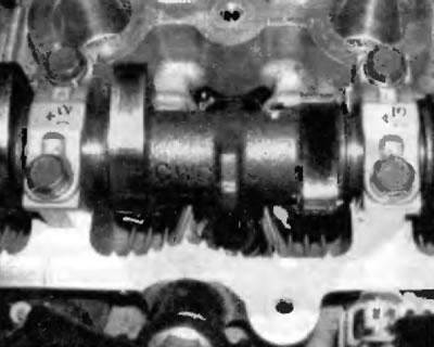
Pic. 7.8. The camshaft bearing caps are numbered and marked with arrows to point towards the end of the engine where the timing chain is located
Warning. Arrange the lids in order. They should be installed in the same places from which they were removed.
9. Loosen the intake camshaft bearing cap bolts in two or three stages, starting at the outer caps and moving towards the center (in reverse order of tightening) (rice. 7.22).
10. Remove the intake camshaft bearing caps, then remove the shaft from the cylinder head. Mark each camshaft by marking it «Inlet» or «Release», so as not to mix up the shafts.
Note. When looking at the engine from the front of the car, the front shaft is the exhaust shaft, and the shaft closest to the baffle is the intake shaft. When installing, be sure to return the camshafts to their original locations.
After removing the camshafts, hang the timing chain with a piece of wire and fix it to some element on the bulkhead (pic. 7.10). This will prevent the timing chain from falling into the engine during other steps. Also cover the opening in the timing chain cover with a rag to prevent any foreign objects from falling into the engine.
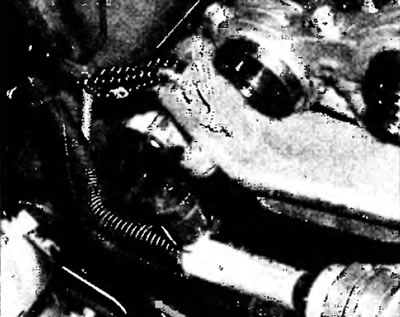
Pic. 7.10. Hang the timing chain aside with a piece of wire and put a rag into the hole in the timing chain cover to prevent foreign objects from falling into the engine
11. Remove the pushrods from the cylinder head by laying them out in order according to the valve and cylinder on which they were installed (pic. 7.11, a, b).
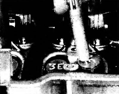
Pic. 7.11, a. Mark pushers appropriately (For example, «I» (Intake) for intake or «E» (Exhaust) for release and their item numbers) and extract them with a magnetic tool
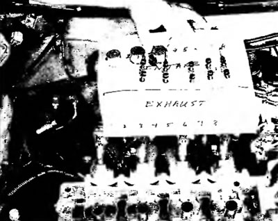
Pic. 7.11b. Label the carton to keep the tappets and bearing caps consistent with their installation order
Warning. Arrange the pushers in order. They should be installed in the same places from which they were removed.
12. Inspect the camshafts, camshaft bearings and tappets as described below. Inspect the camshaft sprockets for wear on the teeth. Inspect the chains for cracks or excessive wear on the rollers, and also for stretching (see paragraph 6). If any elements show signs of excessive wear, they should be replaced.