
24. Position the camshafts so that the dowel pins are at the top in position «12 hours», and then install both camshaft sprockets to their original positions, aligning the dowel pin hole on the back of each sprocket with the dowel pin on the corresponding camshaft. Apply thread locking compound to the threads of the sprocket mounting bolts and install the washers. While holding each camshaft from rotation as described in item 20, tighten the bolts to the prescribed torque listed in the Specifications at the beginning of this chapter.
25. If necessary, turn the camshafts to properly align the SMT marks on the sprockets (pic. 6.8).
26. If the crankshaft is off TDC while performing this procedure, rotate it until the keyway is pointing straight up and in position «12 hours»: the line of symmetry of the groove must be aligned with the center line of the cylinders.
27. Install the fixed timing chain guide (rice. 6.17)
28. Throw the timing chain over the crankshaft sprocket and align the colored link No. 1 (blue or orange) with mark on crankshaft sprocket (pic. 6.28). Install the chain and crankshaft sprocket as a single assembly on the engine, and then install the lower timing chain guide.
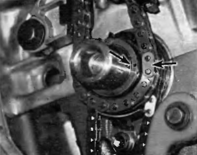
Pic. 6.28. Put the timing chain on the crankshaft sprocket (crankshaft keyway faces straight up) and align the #1 chain link with the mark on the crankshaft sprocket
Note. There are three colored links on the timing chain. Colored link #1 is the link further away from the two colored links that are closer together.
29. Place the timing chain behind the lug of the fixed timing chain guide and slide it onto the exhaust camshaft sprocket and then onto the intake camshaft sprocket, ensuring that the two chain links align with the marks on the camshaft sprockets (pic. 6.29). At the same time, completely eliminate the slack on the right side of the chain.
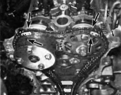
Pic. 6.29. Slide the timing chain onto the exhaust and intake camshaft sprockets while aligning the two chain links with the marks on the camshaft sprockets
30. Using one hand to remove slack on the left side of the chain, install the tensioner arm/timing chain guide. Tighten the pivot bolt to the specified torque given in the Specifications at the beginning of this chapter. After installation, make sure that the lug on the lever cannot move past the stop on the cylinder head (pic. 6.30).
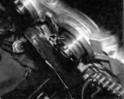
Pic. 6.30. After installing the tensioner arm, make sure that the lug on the arm cannot move past the stopper on the cylinder head
31. Check again that the No. 1 piston is still at TDC on the compression stroke and that the timing marks on the crankshaft and camshaft sprockets are aligned with the colored links.
32. Install the crankshaft position sensor pulse wheel so that the marking «F» was turned outward.
33. Apply a bead of RTV sealant to the sealing surfaces of the timing chain cover where the two center bolts pass and around the perimeter of the cover flange (pic. 6.33, a, b). Install the timing chain cover in place on the engine and screw in the bolts according to their original position.
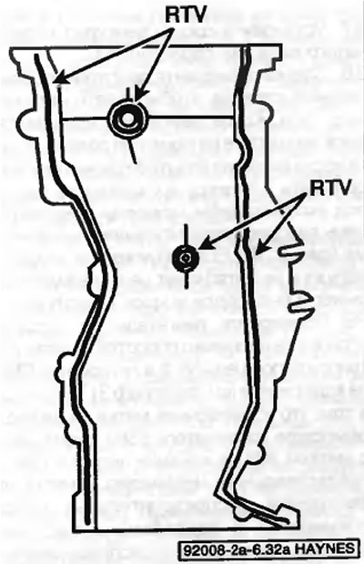
Pic. 6.33 a. Applying sealant to the timing chain cover
Pic. 6.33b. Applying sealant to each side of the parting line between the cylinder head and cylinder block
34. Tighten the bolts evenly in several stages to the prescribed torque specified in Specifications at the beginning of this chapter. Follow the sealant manufacturer's recommendations for assembly technique and sealant cure time.
35. Reload and lock the timing chain tensioner into its «zero» position by doing the following:
- A) Raise the ratchet pawl and push the plunger in until it stops (pic. 6.35).
- b) Insert the hook on the tensioner housing into the pin on the tensioner plunger to lock the plunger in place.
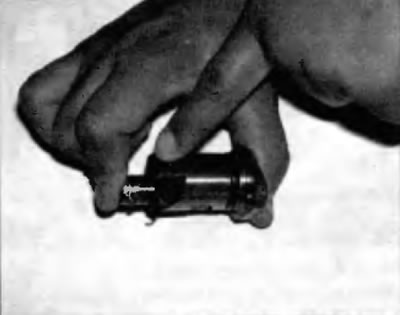
Pic. 6.35. Raise the ratchet pawl and press the plunger inward just enough so that the hook on the tensioner body can engage the pin on the plunger and lock the plunger in place
36. Lubricate the O-ring of the tensioner with a small amount of oil and install the tensioner in the timing chain cover with the hook facing up (pic. 6.36).
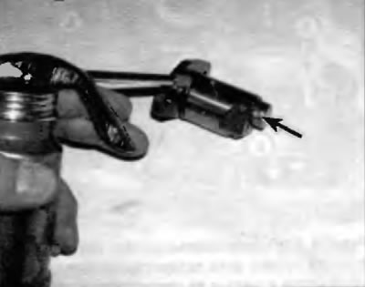
Pic. 6.36. Apply some oil to the O-ring of the tensioner and insert the tensioner into the timing chain cover with the hook facing up
37. Install crankshaft pulley/damper (see paragraph 11).
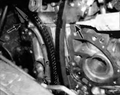
38. Slightly turn the engine counterclockwise to touch the chain tension. As the engine rotates, the hook on the tensioner housing should disengage from the pin on the plunger and allow the plunger to spring out and tension the timing chain (pic. 6.38). If the plunger does not come out and tension the chain, press the lever and release the hook with a screwdriver.
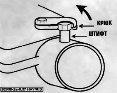
Pic. 6.38. Rotate the engine counterclockwise to disengage the hook from the spring loaded pin on the tensioner, then turn it clockwise and make sure the plunger is out to the lever/ guide rail
39. Turn the engine clockwise a few revolutions and again set the No. 1 piston to TDC on the compression stroke (see paragraph 3). Make sure the alignment mark on the crankshaft pulley/damper is aligned with the mark «0» on the timing chain cover and the marks on the camshaft sprockets are aligned and parallel to the top edge of the timing chain cover as shown (fig 6.8).
40. Tighten the timing chain cover fasteners to the prescribed torque given in the Specifications at the beginning of this chapter (pic. 6.40). The rest of the installation is carried out in the reverse order of removal.
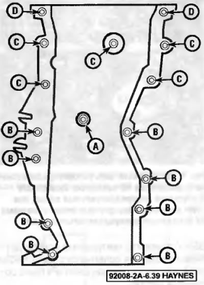
Pic. 6.40. The sequence of tightening the bolts for fastening the hooks of the price of the gas distribution mechanism