
Scheme of car ignition 1980-87
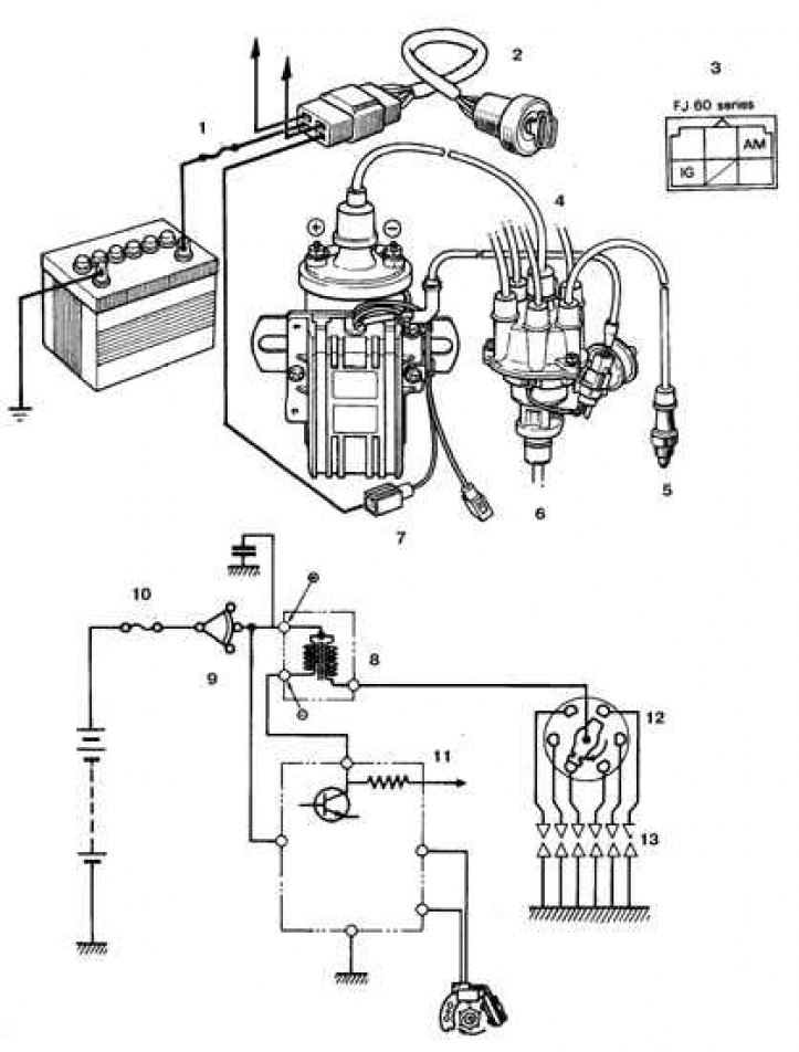
1, 10. Fusible link; 2, 9. Ignition lock; 3. Connector on the side of the lock; 4. Distributor; 5, 13. Candle; 6, 11. To the tachometer; 7. Ignition coil with electronic switch; 8. Coil; 12. Distributor
1988-92 car ignition scheme
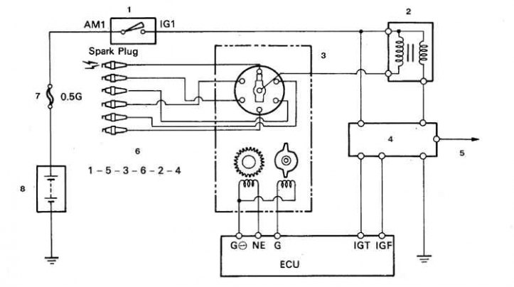
1. Ignition lock; 2. Ignition coil; 3. Distributor; 4. Electronic switch; 5. To the tachometer; 6. Order of work; 7. Fusible link; 8. Battery
1993 car ignition scheme
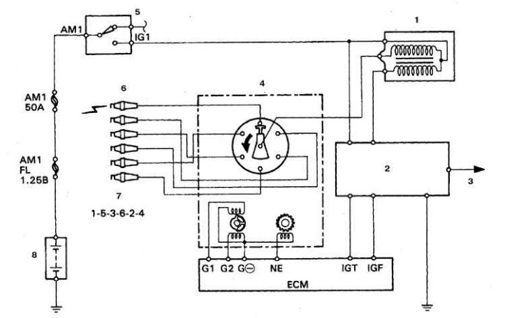
1. Ignition coil; 2. Electronic switch; 3. To the tachometer; 4. Distributor; 5. Ignition lock; 6. Candles; 7. Order of work; 8. Battery
The electronic ignition system includes the ignition switch, battery, electronic ignition unit, Hall sensor (1980-87) or inductive sensor (since 1988), ignition coil, low voltage wires (primary) circuits and high voltage (secondary) chains, ignition distributor and spark plugs.
On vehicles since 1988, the operation of the ignition system is controlled either by a separate processor unit (ECU - unit), or the ECM engine processor unit.
The processor unit provides automatic adjustment of the ignition timing in accordance with signals from sensors that monitor various engine parameters (such as speed, intake air volume, coolant temperature, etc.). Such a system is called an electronic ignition timing system (ESA system).
On the vehicles in question, the ignition coil is mounted separately from the distributor.
Cars 1980-87 equipped with centrifugal and vacuum ignition timing controllers. The electronic ignition switch is mounted on the coil body. The signal sensor on the Hall effect is built into the distributor on the interrupter plate, with which the vacuum regulator rod is rigidly connected (see fig. Car ignition scheme 1980–87).
Cars 1988-92 equipped with an automatic ignition timing system ESA based on an inductive sensor (see fig. 1988-92 car ignition scheme). The electronic ignition switch is mounted on the coil body.
The ignition system of cars from 1993 is similar to that of cars from 1988-92. with the exception that the inductive sensor has an additional winding with a pair of leads G1 and G2 (see fig. 1993 car ignition scheme).
When performing checks and repairs on the ignition system, the following safety rules must be observed (other than those mentioned above).
Connect a tachometer in accordance with the manufacturer's instructions. Some types of tachometers are not compatible with the vehicle's electrical system. Before purchasing a tachometer, consult a car service.
Do not allow ignition coil leads to touch ground. Otherwise, the electronic unit and coil may fail.
Always make sure that the electronic unit is securely connected to ground.