
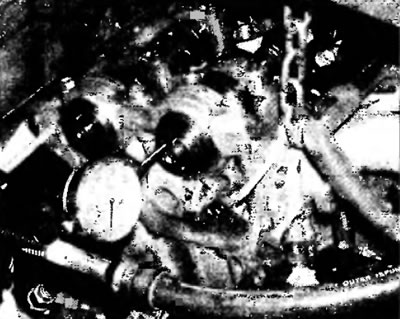
Pic. 7.13. Install a dial gauge as shown to measure the camshaft end play.
14. After removing the camshafts, visually check the running surfaces of the shaft bearings in the cylinder head for signs of pitting, scratches, abrasion or abnormal wear (pic. 7.14). If the running surfaces of the bearing shells are damaged, the cylinder head or No. 1 bearing shells of the intake camshaft may need to be replaced. In this case, they should be replaced with elements of the same size as the original ones.
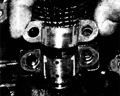
Pic. 7.14. Inspect the running surfaces of the #2-#5 bearing shells in the cylinder head for damage
Note. The size markings are located on the machined surface of the cylinder head near the #1 journals, and the corresponding markings are located on the backs of the bearing shells.
15. Measure the outside diameter of each camshaft journal and record the measurements (pic. 7.15). Compare them with the outer diameters of the journals given in Specifications at the beginning of this chapter, and then measure the inside diameter of each respective camshaft bearing and record the results. Subtract the outside diameter of each shaft journal from the inside diameter of the corresponding bearing bore to determine the radial clearance in each bearing. Compare the results with the prescribed radial clearance values. If any result is outside the standard value, taking into account the wear indicated in this chapter, either the camshaft or the cylinder head, or both, must be replaced.
Note. If tools are not available to make accurate measurements, the Plastigage kit, specially designed for measuring plain bearing clearances, can be used to determine the radial clearance in bearings.
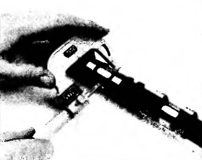
Pic. 7.15. Measure the diameter of each neck with a micrometer. If the diameter is less than the prescribed value, replace the camshaft
16. Measure the height of each camshaft lobe with a micrometer (pic. 7.16). Compare the results with the values given in the Specifications at the beginning of this chapter. If any cam height is less than the prescribed minimum value, replace the camshaft.
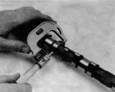
Pic. 7.16. Measure the cam height on each camshaft
17. Check the camshaft runout. To do this, install the camshaft in its original place in the cylinder head and bring the plunger of the dial indicator to the central neck. Reset the indicator scale. Rotate the camshaft slowly and note the dial gauge reading. The runout should not exceed 0.03 mm. If the runout reading exceeds the prescribed value, replace the camshaft.
18. Inspect each pushrod for binding and scratches (pic. 7.18).
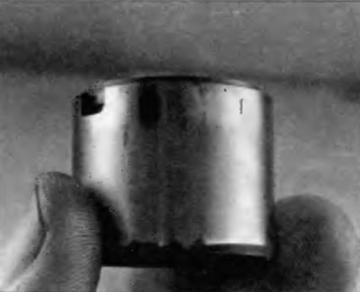
Pic. 7.18. Wipe off oil and inspect each pushrod for wear and tear
19. Measure the outer diameter of each pusher (pic. 7.19) and the inner diameter of the corresponding mounting hole. Subtract the tappet diameter from the bore diameter to determine the radial clearance. Compare the result with the value given in the Specifications at the beginning of this chapter. If the clearance is too large, a new cylinder head and/or new tappets will be required.
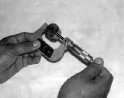
Pic. 7.19. Measure the outer diameter of each pushrod and the inner diameter of the corresponding mounting hole