Design
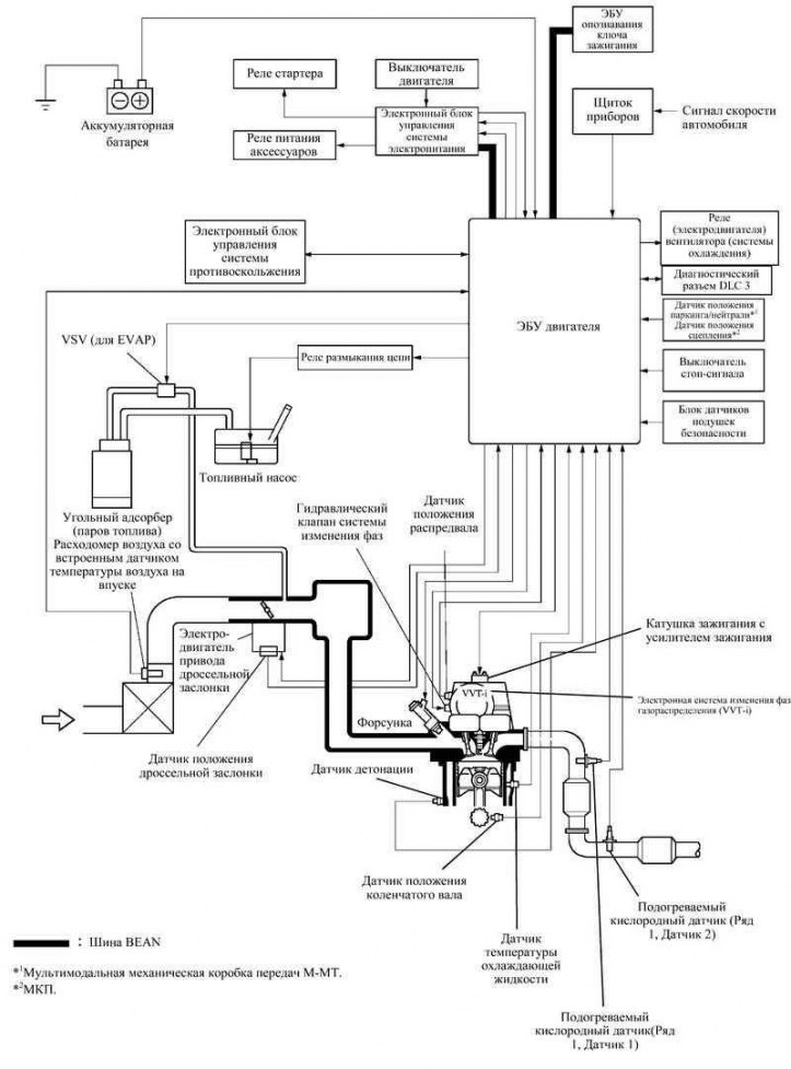
Pic. 2.30. Structural diagram of the engine management system
Figure 2.30 shows the configuration of the electronic engine management system.
The main components of the engine management system
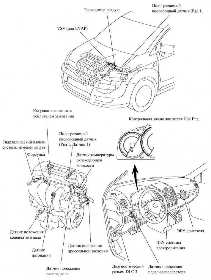
Pic. 2.31. Location of the main components of the engine control system 1ZZ-FE AND 3ZZ-FE
Engine control systems 1ZZ-FE and 3ZZ-FE include units listed in Table 2.6.
Table 2.6. The main components of the engine management system
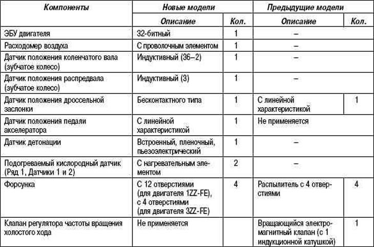
Engine ECU
The engine ECU is based on a 32-bit processor.
Oxygen sensor and air fuel ratio sensor
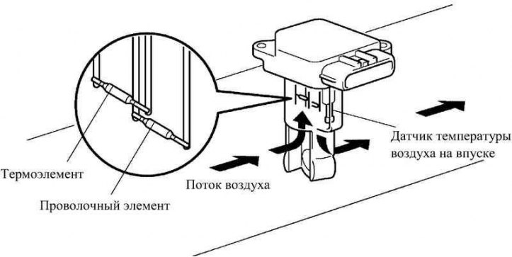
Pic. 2.32. Oxygen sensor and air fuel ratio sensor
A small-sized oxygen sensor and a low-mass air-fuel ratio sensor are installed in the intake manifold. Part of the air entering the engine passes through the measuring area of the sensor (pic. 2.32). Due to the fact that the mass and flow rate of the air entering the engine are measured directly, the measurement accuracy is increased and the resistance that the sensor creates in the intake manifold is reduced.
The sensor has a built-in air temperature sensor.
Crankshaft position sensor
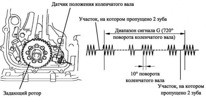
Pic. 2.33. crankshaft position sensor
The crankshaft drive rotor has 34 teeth and a section where 2 teeth are missing. The crankshaft position sensor sends a signal every 10°, and top dead center is determined by the area with missing teeth (pic. 2.33).
Camshaft position sensor
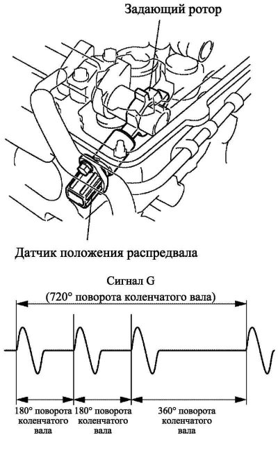
Pic. 2.34. Camshaft position sensor
To determine the position on the intake camshaft, a master rotor is installed, with the help of which 3 pulses are generated for every two revolutions of the crankshaft (pic. 2.34).
Knock sensor (flat type)
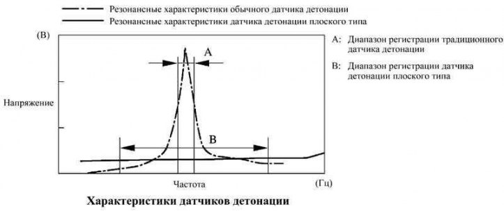
Pic. 2.35. Knock Sensor Performance Chart
In conventional knock sensors (resonant type) there is a plate, the resonant frequency of which coincides with the frequency of detonation of the engine. It allows you to register oscillations near the resonance frequency.
In contrast to this design, a flat knock sensor (non-resonant type) allows you to register vibration in a wider frequency range (approximately 6–15 kHz) and has the following advantages.
Engine knock frequency varies slightly with engine speed. The flat-type knock sensor allows vibration to be detected even when the engine knock frequency changes. Thus, in comparison with traditional knock sensors, the possibilities for registering vibration are expanded, which makes it possible to more accurately adjust the ignition timing.
Design
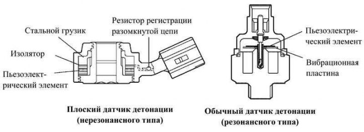
Pic. 2.36. The design of conventional and flat knock sensors
The flat-type knock sensor is attached to the engine with a stud screwed into the cylinder block (pic. 2.36). The stud hole runs through the center of the sensor.
Inside the sensor, in its upper part, a steel weight is installed, which, through an insulator, rests on a piezoelectric element.
An open/short circuit detection resistor is built into the sensor.
Principle of operation
The vibration of the engine detonation is transmitted to a steel weight, which presses on the piezoelectric element. The result is an electromotive force.
Open/Short Circuit Detection Resistor
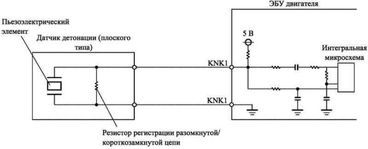
Pic. 2.37. Open/Short Circuit Detection Resistor Block Diagram
When the ignition is on, the knock sensor open/short circuit detection resistor and the resistor in the engine ECU maintain a constant voltage at terminal KNK1. The voltage at the terminal is constantly monitored by the integrated circuit of the engine ECU. If the circuit between the knock sensor and the engine ECU is open or shorted, the voltage at the KNK1 terminal changes and the engine ECU detects an open/short circuit and stores DTC P0325 in memory.
Maintenance recommendation
In connection with the introduction of an open / short circuit resistor into the circuit, the method for checking the sensor has been changed.
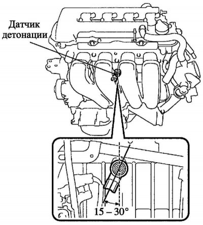
Pic. 2.38. Knock sensor installation diagram
To avoid moisture accumulation in the connector, a flat-type knock sensor should be installed, as shown in Figure 2.38.
Throttle position sensor
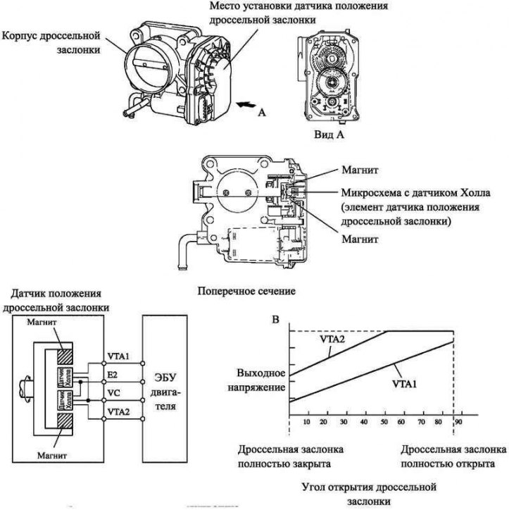
Pic. 2.39. Block diagram and diagram of the operation of the throttle position sensor
The throttle position sensor is mounted on the throttle body. It is designed to determine the opening angle of the throttle valve. Throttle position sensor (Hall Sensor) consists of an integrated circuit with Hall sensors and permanent magnets rotating around it. The magnets are mounted around the throttle valve axis and rotate synchronously with it.
When the throttle opens, the magnets turn with it. Hall sensors detect the change in magnetic flux and generate an output voltage of the appropriate magnitude at terminals VTA1 and VTA2. This signal is used to generate a throttle opening signal to the engine ECU.
This design not only ensures high accuracy of throttle position detection, but is also simple and reliable because it uses a non-contact principle. In addition, in order to improve the reliability of the sensor, two systems with different output characteristics are used to generate output signals.
Maintenance recommendation
Since the sensor uses a Hall sensor chip, the test method is different from the test method for a conventional throttle position sensor.
Accelerator pedal position sensor
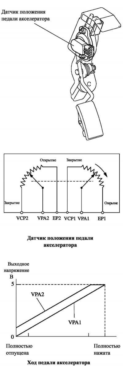
Pic. 2.40. Block diagram and diagram of the operation of the accelerator pedal position sensor
The accelerator pedal position sensor converts the pedal stroke into electrical signals with two different characteristics and transmits them to the engine ECU. The VPA1 signal has a linear characteristic and is applied throughout the entire stroke of the accelerator pedal. The VPA2 signal has a biased voltage characteristic.
EFI electronic injection
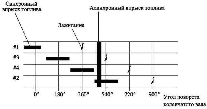
Pic. 2.41. Diagram of synchronous and asynchronous injections
The L-type EFI system directly senses the mass of air entering the engine using a wire-wound air mass meter.
Distributed injection system is used (when fuel is injected into each cylinder once every two revolutions of the crankshaft).
There are two types of fuel injection:
- the first method is synchronous injection, when the main injection duration is corrected based on the signals from the sensors. in this case, the injection is carried out in the same position of the crankshaft;
- the second method is asynchronous injection, when a single injection moment for all injectors is determined by signals from sensors, regardless of the position of the crankshaft. To reduce engine wear and fuel consumption, the system turns on the fuel supply under certain driving conditions.
At low coolant temperatures and while the engine is running at low speeds, the system provides injection of additional fuel.
Intelligent Electronic Throttle Control System ETCS-i
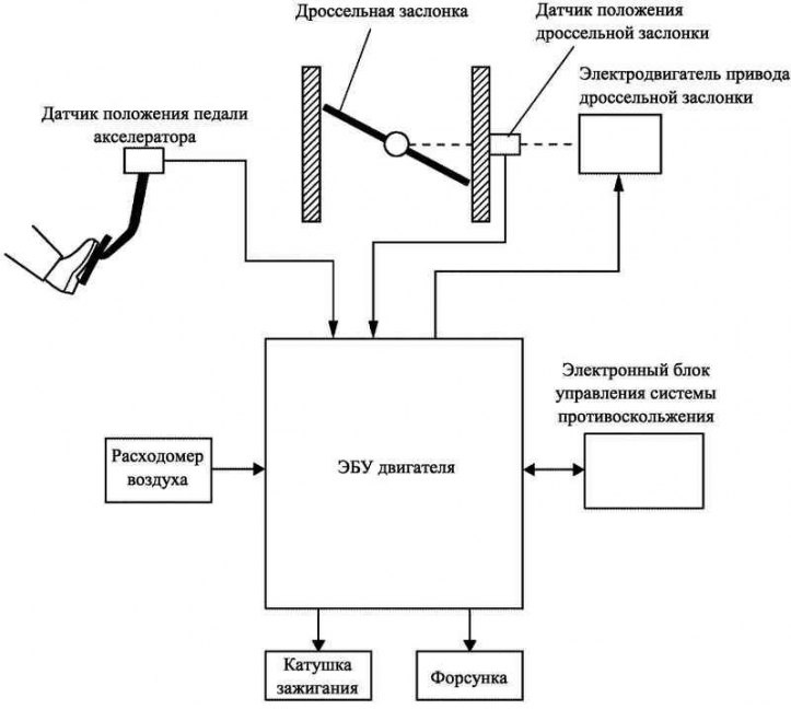
Pic. 2.42. Structural diagram of the system
ETCS-i provides exceptional throttle position control in all engine operating conditions. The new 1ZZ-FE and 3ZZ-FE engines do not have mechanical throttle control, and a pedal position sensor is installed on the accelerator pedal.
In a conventional throttle body system, the throttle opening angle is determined by the stroke of the accelerator pedal. In contrast, in ETCS-i, the engine ECU calculates the optimum throttle position based on driving conditions and sets it by controlling the drive motor.
The ETCS-i system provides control of the ISC idle system, cruise control system, TRC traction control system and VSC stability control system.
In the event of a malfunction, the system goes into emergency mode.
Principle of operation
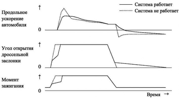
Pic. 2.43. Diagram of the operation of the control system during acceleration and deceleration
Depending on the operating mode, the engine ECU determines the required throttle opening angle and controls the throttle actuator motor. The modes for which the engine ECU is responsible are listed below.
- non-linear mode.
- idle mode.
- Throttle control during traction control (TRC).
- Coordination mode with VSC system.
- Cruise control.
Nonlinear mode
The system adjusts the throttle to the optimum position according to driving conditions, i.e. accelerator pedal position and engine speed, providing precise throttle control and comfortable driving in all modes.
Idle mode
The engine ECU regulates the throttle position to maintain the optimum idle speed at all times.
Throttle control
during operation of the traction control system (TRC)
If traction control is on (TRC), when the drive wheel slip is significant, the skid control ECU sends a signal to close the throttle, thereby helping to maintain vehicle control and traction on the wheels.
Coordination mode with VSC system
To improve the efficiency of the VSC system, the throttle position is controlled in conjunction with the skid control ECU.
Cruise control
The engine ECU with integrated cruise control ECU directly controls the throttle position to maintain a constant speed.
Operation of the accelerator pedal position sensor in emergency mode
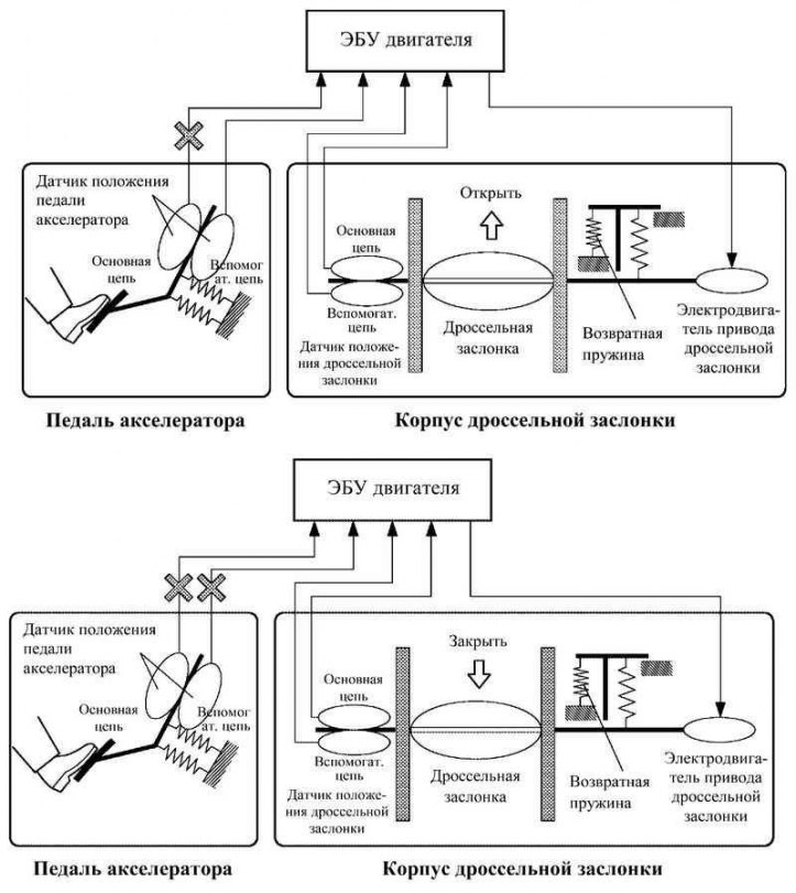
Pic. 2.44. Scheme of operation of the accelerator pedal position sensor in emergency mode
There are two circuits for signaling the accelerator pedal position sensor (main and auxiliary). If one of the sensor circuits fails, the engine ECU detects an incorrect voltage difference between the signals in the two circuits and switches to emergency mode. to maintain the ability to drive the vehicle in emergency mode, an intact circuit is used to determine the position of the accelerator pedal.
If both sensor circuits are faulty, the engine ECU recognizes incorrect signal voltages on both circuits and disables the throttle control system. In this mode, the car can move with a crankshaft speed equal to the idle speed.
There are two circuits for transmitting the throttle position sensor signal (main and auxiliary). If one of the sensor circuits fails, the engine ECU detects an incorrect voltage difference between the signals in both circuits, turns off the power to the throttle motor and switches to emergency mode. In this case, under the influence of a return spring, the throttle valve is set to a predetermined slightly open position. Thus, the car can move in emergency mode. In this case, engine power is regulated by changing the volume of injected fuel and changing the ignition timing, depending on the position of the accelerator pedal.
In the same mode, control will be carried out if the ECU detects a malfunction of the throttle actuator motor.
Electronic variable valve timing system WT-i
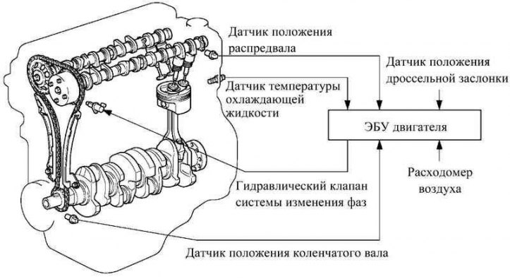
Pic. 2.45. Scheme of operation of the electronic system for changing the valve timing WT-i
The VVT-i system is designed to adjust the angle of rotation of the intake camshaft in the range of 40° (angle of rotation of the crankshaft) and installation of valve timing, optimally corresponding to the operating modes of the engine. The system allows you to increase torque at any speed of the crankshaft, and also helps to reduce fuel consumption and reduce the content of harmful substances in exhaust gases (pic. 2.45).
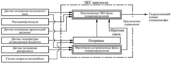
Pic. 2.46. Block diagram of the electronic variable valve timing system WT-i
Based on the engine speed, the amount of air entering the engine, the throttle position and the coolant temperature, the engine ECU determines the optimal valve timing for all engine operating conditions and controls the hydraulic phase change valve. In addition, by processing the signals from the camshaft and crankshaft position sensors, the engine ECU determines the actually set valve timing, providing feedback in the control of the valve timing (pic. 2.46).
WT-i control unit
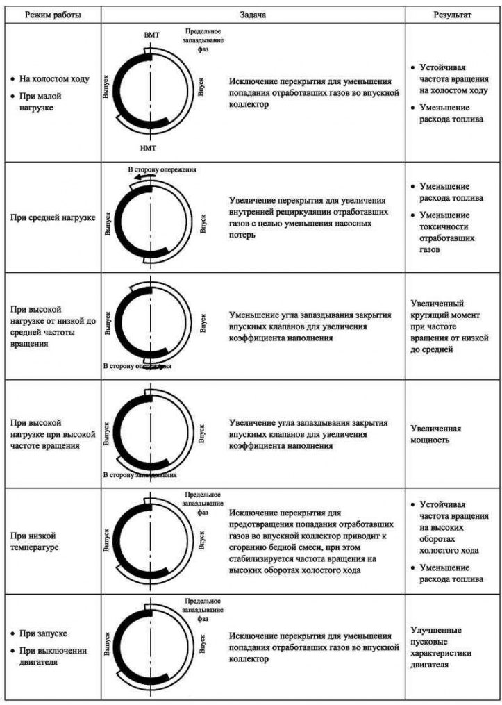
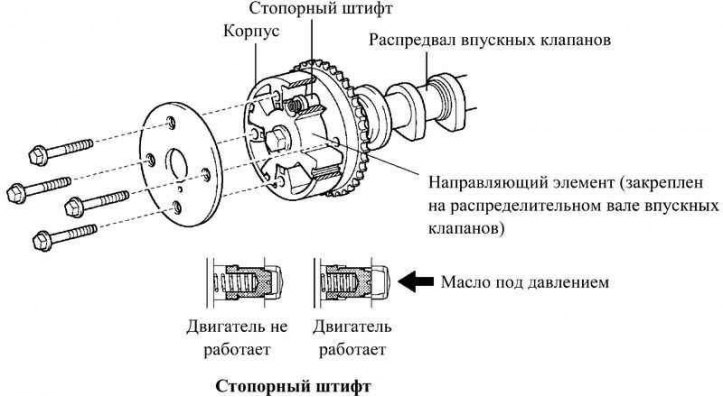
Pic. 2.47. The result of the WT-i system
The control unit consists of a housing driven by a valve train chain and a guide vane connected to the intake camshaft.
Pressurized oil flows through the intake camshaft port to a hydraulic valve controlled by the engine ECU. The valve then redistributes the oil, depending on the ECU commands, either into the advance or lag channels of the intake valves, which in turn leads to the rotation of the WT-i guide element, while providing a stepless change in the valve timing of the intake valves.
When the engine is not running, the intake camshaft is in its most retarded position for the best starting performance.
If the VVT-i control unit is not supplied with pressurized oil immediately after starting the engine, the locking pin blocks the rotation of the VVT-i control unit, preventing detonation.
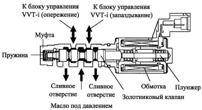
Hydraulic phase change valve
The hydraulic phase change valve controls the position of the spool valve in accordance with the cyclic commands of the engine ECU. As a result, pressurized oil is supplied to the WT-i controller to turn the camshaft forward or retard. When the engine is not running, the hydraulic variable valve timing is in the most retarded position.
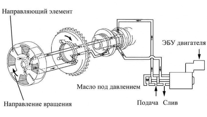
Principle of operation (advance)
Pic. 2.48. WT-i control unit
If the hydraulic valve for timing change under the influence of advance signals from the engine ECU is located as shown in Figure 2.48, the resulting oil pressure is supplied to the guide element from the advance side, while the camshaft rotates in the direction of advancing the opening angle of the valves.
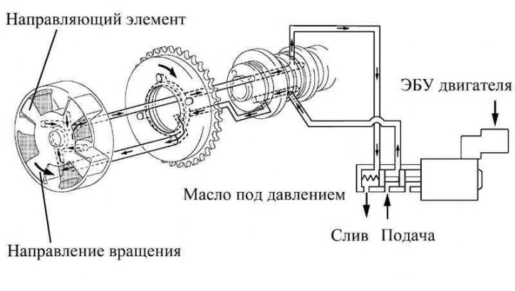
Principle of operation (lag)
Pic. 2.49. Spool valve phase change diagram
If the hydraulic valve for phase change under the influence of lag signals from the engine ECU is located as shown in Figure 2.49, then oil under pressure is supplied to the guide element from the lag side, while the camshaft rotates in the direction of the valve opening angle lag.
Pic. 2.50. Valve opening angle advance direction
Pic. 2.51. Direction of valve opening angle delay
Fixation of the shaft in the installed position
Once the camshaft is in the desired position, the hydraulic camshaft valve is in neutral, locking the camshaft until driving conditions change. In this way, the valve timing is regulated and unnecessary leakage of engine oil is prevented at the moment.
Fuel pump control
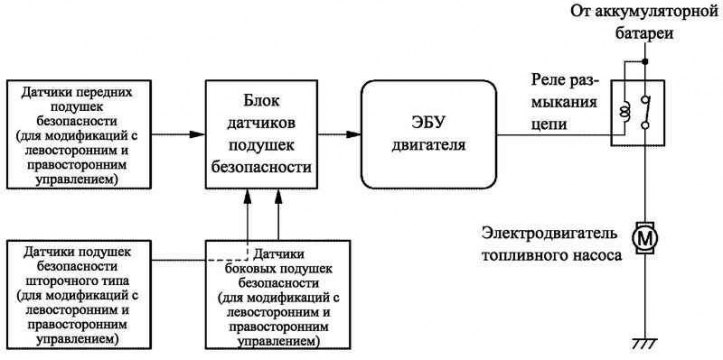
Pic. 2.52. Fuel pump control block diagram
In the event of an airbag deployment in a frontal or side collision, a fuel cut-off function is provided with the fuel pump turned off. The function is activated by the airbag deployment signal from the airbag sensor unit, which is registered by the engine ECU; The engine ECU turns off the circuit opening relay. After turning off the fuel supply, you can resume and start the engine by turning the key in the ignition switch from the OFF position to the ON position.
Air conditioner shutdown control
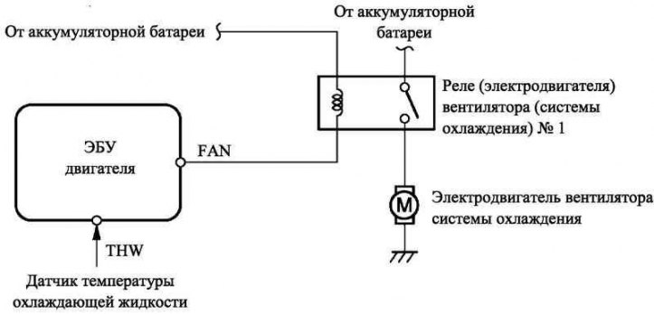
Pic. 2.53. Connection diagram for models without air conditioning
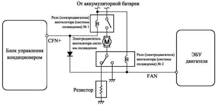
Pic. 2.54. Connection diagram on models with air conditioning
On models without air conditioning, the engine ECU controls the cooling fan speed based on the engine coolant temperature sensor.
Air-conditioned models have two cooling fan speeds: low and high. The engine ECU commands the high speed to be activated depending on the signals from the cooling fluid temperature sensor and the A/C pressure sensor. The low speed control is carried out by the air conditioning control unit.
Starter control function «Semi-automatic start»
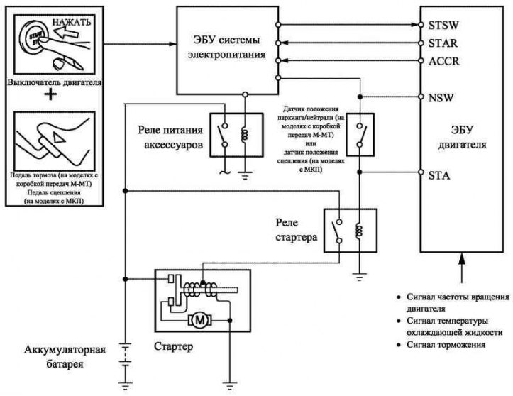
Pic. 2.55. Block diagram of the starter control system
The new car model uses the starter control function «Semi-automatic start». When the engine start button is pressed, this function is active until the engine starts. The brake pedal must be pressed (on models with M-MT multimodal manual transmission) or clutch pedal (on models with manual gearbox). Thus, the reliability of starting the engine is increased and the possibility of the starter operation after starting the engine is excluded.
If the engine ECU receives a start signal from the power ECU, the system monitors the engine speed signal (NE) and does not turn off the starter until the engine starts. Also, if the engine ECU receives a start signal from the power ECU, but determines that the engine is already running, it will not engage the starter.
Principle of operation
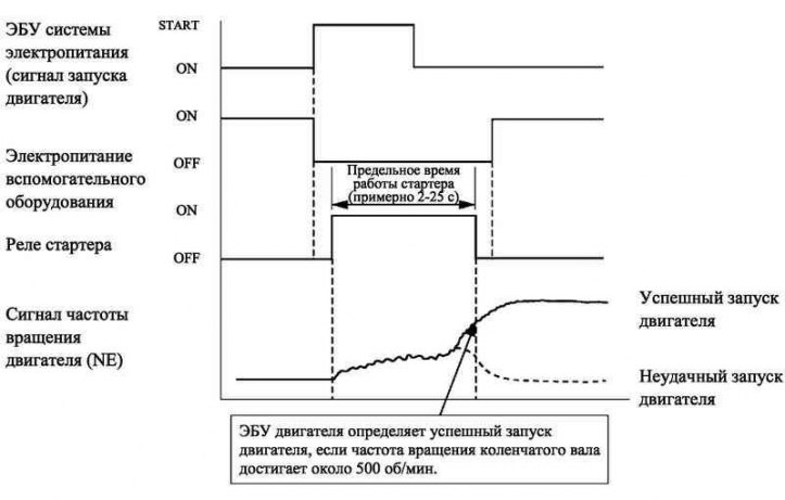
Pic. 2.56. Diagram of the operation of the starter control system
As shown in figure 2.56, when the engine ECU receives the start signal (STSW) from the power ECU, the engine ECU sends STAR and ACCR signals to the power ECU. The latter, in turn, sends a signal to the starter relay to turn on the starter. If the engine is already running, the engine ECU does not supply the STAR and ACCR signals to the power ECU. Therefore, the power control ECU does not supply power to the starter relay.
After turning on the starter and after the engine speed exceeds approximately 500 min–1, the engine ECU detects that the engine is running and disengages the starter.
If the engine has a fault and does not start, the starter will operate for the maximum allowable time, after which it will automatically disengage. The maximum starter running time is approximately 2 to 25 seconds, depending on the coolant temperature. If the coolant temperature is very low, the starter runs for about 25 seconds, and when the engine is warm enough, the starter runs for no more than 2 seconds.
In order to eliminate additional load during unstable voltage during engine start, the system cuts off power to auxiliary equipment during this time.
The system provides the following levels of protection:
- if the engine is already running, the starter will not turn on even if the ignition key is turned to the START position;
- even if the driver holds the key in the ignition switch in the START position, after the engine is started from half a turn, the engine ECU will turn off the starter when the engine speed reaches approximately 1200 rpm–1 or more;
- even if the driver holds the ignition key in the START position and the engine does not start, the engine ECU will turn off the starter after about 30 seconds;
- If the engine ECU does not receive an engine speed signal while the starter is running, it will immediately stop outputting the STAR and ACCR signals.
Diagnostics
Diagnostic system type EURO-OBD (European system of on-board diagnostics), used on 1ZZ-FE and 3ZZ-FE engines, meets the requirements of European regulations.
If the engine ECU detects a problem, it diagnoses and logs the problem node. In addition, to inform the driver on the instrument panel, the Chk Eng engine warning lamp turns on constantly or starts flashing.
The engine ECU also stores electronic DTCs for all faults. These codes can be read using the microprocessor tester P.
All DTCs comply with SAE codes. Some DTCs have been broken down into smaller sub-sections than previously, with new DTCs assigned to the sub-sections.
Maintenance recommendation
To clear the electronic DTCs stored in the engine-ECU memory, use the smart tester II, or disconnect the battery terminal, or remove the EFI fuse for at least a minute.
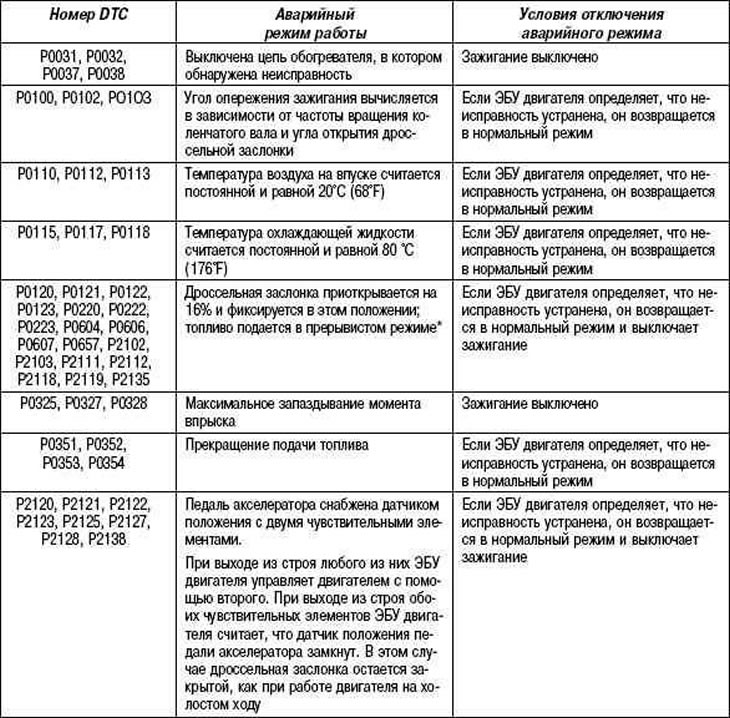
System operation in emergency mode
When a malfunction is detected, the engine ECU turns off or puts the engine into emergency operation according to the data recorded in the memory.
Table 2.9. System operation in emergency mode