



2. On 2.0L engines produced since 2001, gradually and evenly loosen and then remove the eleven lower crankcase-to-cylinder block bolts, noting that the bolts are of varying lengths. Using a flat-blade screwdriver, carefully pry the lower crankcase away from the cylinder block, resting against the special lugs (see figure 12.2, a, b).
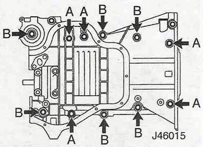
Figure 12.2,a. Location of the engine block lower crankcase mounting bolts - 2.0L models produced since 2001:
A - long bolts;
B - short bolts.
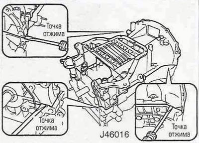
Figure 12.2, b. Removing the lower crankcase from the cylinder block - engines produced since 2001 with a volume of 2.0 liters.
Remove the sealing gasket from the mating flange on the oil filter side and remove the crankshaft oil seal.
3. Please note that the upper, unworn band (the "fire band") of the cylinder can damage the piston or the rings when removing it, so it must be removed using a special reamer. However, it's also worth noting that such wear on the cylinder will require reaming or replacing the cylinder liners, which means replacing both the pistons and rings.
4. Use quick-drying paint or a center punch to mark the machined surfaces of the connecting rods and their caps. Number them, keeping in mind that cylinder numbering starts on the timing side. Check for any old markings—the engine may have been disassembled.
5. Turn the crankshaft to set pistons No. 1 and 4 to BDC (bottom dead center).
6. Loosen the connecting rod cap bolts/nuts and remove the caps one by one, together with the lower bearing shell (see figure 12.6, a, b).
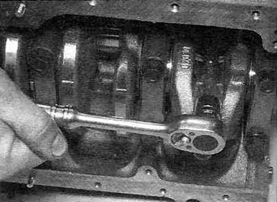
Figure 12.6,a. Loosening the nuts/bolts securing the bearing cap of the lower head of the connecting rod of piston No. 1.
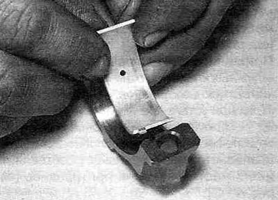
Figure 12.6,b. Removing the lower bearing shell from the connecting rod lower head bearing cap.
If the operation is undertaken only to replace the bearings, move the connecting rod away from the crankshaft and remove the upper bearing. If the liners are to be reinstalled, tape them to the corresponding covers. This should be done in order to be able to carry out a more complete diagnosis. Please note that the bolts/nuts securing the lower connecting rod caps must be replaced as a set during assembly.
7. To avoid damaging the surfaces of the crankpins, wrap the threaded studs of the connecting rods (if the covers are secured with nuts) with electrical tape or put pieces of plastic tubing on them.
8. Using the hammer handle, push the piston down the cylinder, removing it from the top of the block. Remove the upper bearing shell and tape it to the crank arm so it doesn't get lost (see Figure 12.8).
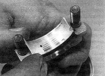
Figure 12.8. Removing the upper shell from the connecting rod bearing.
9. Place the lower cover on the connecting rod, tightening the mounting nuts/bolts. Store the removed parts so as not to mix them up.
10. Remove piston No. 4 in the same way.
11. Turn the crankshaft 180°, set pistons No. 2 and 3 to BDC and remove them (the method is described above).