
Note. Removing the engine on these cars is a harder job, especially for a home mechanic working from home. Due to the design of the vehicle, the manufacturer prescribes to remove the engine assembly with the gearbox (in block with drive axle) as a single unit from the bottom of the car, and not to extract from the top. With a floor jack and secure supports, the vehicle cannot be raised high enough or supported safely enough to remove the engine/transmission assembly from underneath the vehicle. The manufacturer recommends that the removal of the engine assembly with the gearbox be carried out only with the help of a frame-type vehicle lift.
Note. Keep in mind that when performing this procedure, you will need to adjust the height of the vehicle using a vehicle lift in order to perform some of the steps.
Removing
1. Place the vehicle over a repair type vehicle lift, move the lift arms under the jacking position on the vehicle. Raise the lift arms until they are in contact with the vehicle, but not so far that the vehicle's wheels are off the floor.
2. Relieve pressure in the fuel system (see chapter 4).
3. On 2004 and later V6 Highlander models and all Lexus models, remove the bonnet top panel/air box deflector (see chapter 11).
4. On 2004 and later V6 Highlander models and all Lexus models, remove the windshield wiper arms and windshield wiper motor (see chapter 12).
5. Not Highlander models with VB engine 2004 and later and all Lexus models, remove the lower hood panel (see chapter 11).
6. Remove the battery and battery shelf (see chapter 5).
7. Remove the air filter housing and intake air line (see chapter 4).
8. Disconnect the accelerator cable from the throttle body (see chapter 4) (in the presence of).
9. Disconnected the cruise control cable from the throttle body (in the presence of).
10. Disconnect the shift cable from the transaxle (see chapter 7).
11. Remove the generator (see chapter 5).
12. Remove the air conditioning compressor without disconnecting the refrigerant lines from it (see chapter 3). Tie the compressor aside (but not to the subframe).
13. Disconnect the intermediate shaft from the steering gear (see chapter 10).
14. Disconnect the supply fuel hose from the fuel rail (see chapter 4). Shut off the line and fitting.
15. Clearly mark all detachable elements with labels and stickers, disconnect all vacuum lines and hoses of the emission reduction systems, disconnect the electrical connectors and disconnect the mass tires connecting the engine and gearbox to the vehicle chassis. Masking tape and/or paint is well suited for marking elements (pic. 7.15). If necessary, take photographs or pencil sketches of the location of elements and brackets.
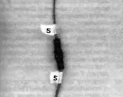
Ryas. 7.15. Mark both ends of each wire or hose before disconnecting it
16. Using a syringe, pump out as much fluid as possible from the power steering reservoir. Disconnect the power steering hose from the return line.
17. Remove engine mount tie rod (see chapter 2A or 2B). Also remove the appropriate support bracket from the cylinder head.
18. Disconnect wiring from main fuse/relay box in engine room (see chapter 5. fig. 4.4, b). Disconnect all other electrical connectors installed in the wiring harness going to the PCM.
19. Loosen the front wheel nuts and axle/hub nuts (see chapter 8).
20. Raise the car on a lift and remove the front wheels.
21. Remove the sections of the lower engine protection (see chapter 2A or 2B). Also remove the lockers and seals of the wing aprons (see chapter 11).
22. Disconnect the stabilizer links from the anti-roll bar and the tie rod ends from the steering knuckles (see chapter 10).
23. Remove axle shafts (see chapter 8).
24. On all-wheel drive models, remove the propeller shaft (see chapter 8).
25. On all-wheel drive models, drain the oil from the transfer case (see chapter 1).
26. Drain engine coolant (see chapter 1).
27. Drain engine oil (see chapter 1).
28. On models with four-cylinder engines, disconnect the lines from the separately installed oil cooler (see chapter 3).
29. Drain the oil from the gearbox in the block with the drive axle (see chapter 1).
30. Turn out bolts of fastening of a faceplate to the hydrotransformer (pic. 7.30, a, b). Also disconnect the hoses from the transmission fluid heat exchanger (see chapter 7).
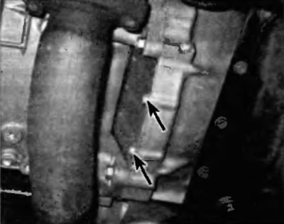
Pic. 7.30 a.m. Turn out bolts of fastening of a technological cover on the front section of the gearbox housing in the block with the driving axle...
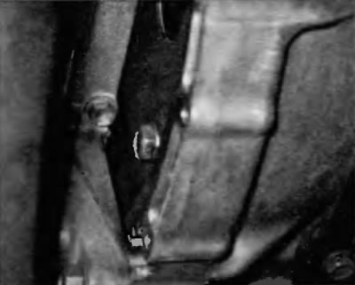
Pic. 7.30.6.... then remove the torque converter mounting bolts
31. Disconnect the hydraulic lines from the power steering pump. Disconnect the pressure and return lines from the power steering.
32. Remove the appropriate bolts and disconnect the exhaust pipe from the exhaust manifold assembly with catalytic converter (if necessary on two rows of cylinders (see chapter 2A or 2B), and then remove the front section of the exhaust system (see chapter 4).
33. Lower the car and disconnect the radiator hoses and heater hoses from the engine. Remove the radiator (see chapter 3).
34. Support the engine/gearbox assembly from above with a lifting device. Attach the hoist chain to the rigging brackets. If rigging brackets or hooks are not provided, lifting hooks are available from an auto parts store or dealer's parts department. Alternatively, you can attach chains to some of the engine parts that are strong enough to bear the weight of the engine and positioned for good balance. If you are attaching the chain to a stud on the engine or using a bolt that goes through the chain and enters a threaded hole, place a washer between the nut/bolt head and the chain and tighten the nut or bolt securely.
Attention! Do not work under the engine/gearbox when the unit is only supported by a lifting device.
35. Take up any slack in the lifting device's chains/lanyards, but only enough to cause only slight tension. Position the chain/slings on the hoist so that the engine/gearbox assembly is in a horizontal balance position.
Note. Depending on the design of the engine hoist, it may be useful to position the hoist on the side of the vehicle so that the unit is between the hoist legs when the engine/transmission assembly is lowered.
Note. The slings or chain must be long enough to allow the engine/transmission assembly to be lowered using a lifting device so that the lift arm is clear of the vehicle.
36. Support the subframe with a pair of floor jacks. Check again that there are no hoses or electrical wiring between the subframe and the vehicle. Turn out bolts and remove support of the power unit from a stretcher (see chapter 2A or 2B). Turn out bolts of fastening of a subframe (see chapter 10) and lower it to the floor, and then remove it from under the car.
Attention! Depending on the design of the engine lift, this may be difficult, but be sure to securely support the subframe before removing the subframe mounting bolts.
37. Once again, make sure that there are no elements connecting the engine or gearbox to the car. If necessary, disconnect everything that prevents the removal of the engine, marking the connections with suitable labels.
38. Lower the engine assembly with the gearbox (pic. 7.38). Once the engine/transmission assembly is lowered to the floor, disengage the lifting device chains/slings from the engine assembly and raise the vehicle just enough so that the power unit can be removed from under the vehicle.
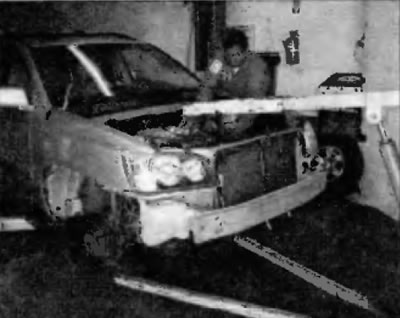
Pic. 7.38. After removing the subframe, lower the engine assembly with gearbox to the floor
39. Reattach the chain or slings to support the engine/gearbox assembly.
40. Raise the engine/gearbox assembly, then place blocks of wood or other floor jack under the engine without removing the slings or chain from the engine. Support the transaxle with another floor jack, preferably with a special transaxle jack head adapter. At this point, you can unscrew the corresponding bolts and remove the transfer case (4WD models - see chapter 7). Be very careful to make sure that the supports under the elements are secure so that they do not tip over when detaching.
41. Turn out bolts of fastening of a transmission in the block with a leading bridge to the engine and separate a transmission from the engine.
42. Connect the lift chain to the engine, then lift the engine and secure it to a suitable stand.
Installation
43. Installation is carried out in the reverse order of removal, taking into account the following points:
- A) Check the engine/gearbox mounts in the drive axle unit. If they are worn or damaged, replace them.
- b) Connect the transaxle to the engine following the procedure described in chapter 7.
- V) When installing the subframe, tighten the subframe mounting bolts to the prescribed torque specified in Specifications at the beginning of this chapter.
- G) Tighten the axle/hub nuts to the specified torque as specified in Specifications at the beginning of this chapter. Tighten all steering gear and suspension fittings to the specified torque as specified in Specifications at the beginning of this chapter. Tighten the wheel nuts to the specified torque specified in Specifications at the beginning of this chapter
- d) Fill the engine with coolant and oil. Pour working fluid into the power steering reservoir. Fill transmission oil into the transaxle (see chapter 1).
- e) Connect battery (see paragraph 1 of chapter 5).
- and) Start the engine and check for correct operation. Check the engine for leaks. Shut off the engine and check fluid levels again.