
8. Position the cylinder block with the bottom up.
9. Turn out bolts and remove covers of radical bearings.
10. Remove «old» bearing shells in the cylinder block and from the main bearing caps, if they are still in their original places. Wipe the bearing surfaces in the block and covers with a clean, lint-free cloth. These surfaces must be kept immaculately clean. This is very important for setting the correct radial clearance in the bearings.
Checking radial clearances in main bearings
11. Clean the backs of the new upper main bearing shells (with grooves and lubrication holes) and install each on a regular place in the block. Be careful not to mix them up. Each upper bearing has an oil groove and an oil hole
Warning. The lubrication holes in the cylinder block must be aligned with the lubrication holes in the upper bearing shells.
If you are running a V6 engine, the thrust bearings (washers) should be installed in the cover and seat in block No. 2. On four-cylinder engines, thrust bearings (washers) should be installed in cover no. 3 (central). Install the thrust washers with the grooved side facing out. Install the thrust washers so that one set is located in the block, the other set is located in the main bearing cap. Clean the backsides of the lower main bearing shells (without grooves) and invest in the appropriate niches. Make sure that the protrusion on the bearing shell fits into the recess in the cylinder block or main bearing cap.
Warning. Do not use a hammer to drive the bearing shells into place and do not damage the running surfaces Do not apply lubricant at this stage.
12. Clean the surfaces of the liners in the cylinder block and the crankshaft main journals with a clean, lint-free cloth
13. Check or clean the oil holes in the crankshaft, as any dirt present there can only go one way - right through the new liners.
14. After thoroughly cleaning the crankshaft, put it in its original place in the cylinder block
15. Before the final installation of the crankshaft, check the radial clearance in the main bearings.
16. Cut a few strands of Plestigage to the appropriate size (from the kit for measuring clearances in plain bearings). They should be slightly shorter than the width of the root neck.
17. Install one thread on each main journal of the crankshaft, parallel to the axis of the journal (pic. 11.17).
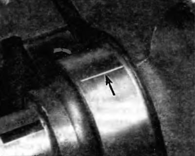
Ryas. 11.17. Place five Plastigages on the main bearing journal as shown
18. Clean the surfaces of the bearing shells in the main bearing caps. Hold the liners and install the covers on the crankshaft and cylinder block. Do not move the Plastigage threads. Be sure the covers are installed with the arrows facing the front of the engine.
19. Before screwing in the bolts, apply clean engine oil to their threads, and then hand-tighten the bolts. Tighten the main bearing cap bolts in two stages in the sequence shown (pic. 11.19, a-c) prescribed force specified in Specifications at the beginning of this chapter. Do not rotate the crankshaft during this operation.
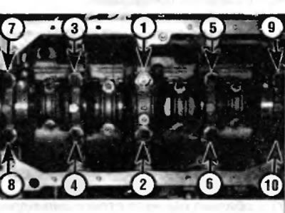
Pic. 11.19 a. Main Bearing Cap Bolt Torque Sequence - Four-Cylinder Engines
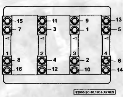
Ryas. 11.19, b. Main Bearing Cap Bolt Torque Sequence - V6 Models
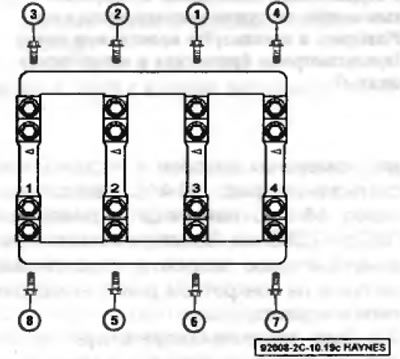
Rns. 11.19, c. Main Bearing Cap Side Bolt Torque Sequence - V6 Models
20. Remove the bolts, working in reverse tightening sequence, and carefully remove the main bearing caps, pointing each straight up and away from the block. Do not dislodge the Plastigage threads or rotate the crankshaft. If the bearing cap does not come off, gently tap it on both sides with a soft-faced hammer to pry it off.
21. Compare the width of the split Plastigage thread with the scale printed on the edge of the package for the plain bearing gap measurement kit (pic. 11.21). A typical main bearing radial clearance should be in the range of 0.04-0.06 mm. Consult your dealer for exact main bearing clearance on a specific engine.
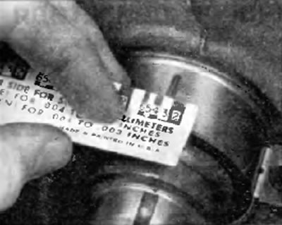
Pic. 11.21. Estimate the radial clearance of the bearing using the scale on the packaging of the kit for measuring clearances in plain bearings. Measure at the widest part of the Plastigage thread and use the correct scale (imperial and metric scales available)
22. If the clearance is not correct, this may be due to the wrong size of the bearing shells (so you need other inserts). Before deciding on the need to use other liners, make sure that there is no dirt or oil between the liners and the cover or cylinder block at the time of measuring the gap. If one end of the Plastigage thread is wider than the other, the neck may be tapered. If the clearance still exceeds the prescribed limit, the bearings must be replaced with bearings of reduced oversize.
Warning. When installing a new crankshaft, use a standard size bearing set.
23. Carefully remove any Plastigage slack from the main journals and/or bearing shells. Make sure the oil holes are clean. Be very careful not to scratch the bearing by using your fingernail or the edge of a plastic card.
Final installation
24. Carefully remove the crankshaft from the cylinder block.
25. Clean the bearing shell surfaces in the cylinder block, then apply a thin, even coat of molybdenum-based grease or engine oil to each of the bearing surfaces. Apply grease to the thrust surfaces as well as the journal surfaces mating with the thrust bearing.
26. Clear necks of a cranked shaft and put a cranked shaft on a regular place in the block of cylinders.
27. Clean the surfaces of the bearing shells and apply the same grease to them.
28. Hold the bearing shells in place and install the main bearing caps on the crankshaft and cylinder block. Correct the position of the bearing caps in place using a brass punch or soft-faced hammer.
29. Apply clean engine oil to the threads of the bolt, wipe off excess oil, and then install the bolts and hand-tighten them.
30. Tighten the main bearing cap bolts in sequence (pic. 11.19 a or 11.19 b) force 13 or 16 Nm.
31. Use a screwdriver or pry bar to press the crankshaft forward so that the thrust bearing assumes the specified position. After the crankshaft has been retracted fully forward, put the screwdriver in place so that the force remains applied to the crankshaft until all main bearing cap bolts are fully tightened.
32. Tighten the main bearing cap bolts in two stages in the sequence shown (pic. 11.19 a or 11.19 b) prescribed force and to a given angle in accordance with specifications at the beginning of this chapter. On V6 engines, tighten the side bolts last (pic. 11.19, a).
33. Again check up an axial backlash of a cranked shaft by means of a feeler gauge or a pointer indicator. If the thrust surfaces of the crankshaft are not worn or damaged and new bearings have been installed on them, the axial clearance should be correct.
34. Turn the crankshaft several times by hand to boil it for possible jamming. The torque must not exceed 5.6 Nm. If the cranking torque is too high, immediately find out and eliminate the cause of this.
35. Install a new rear cuff (see chapter 2A or 2B).