
26. Remove the cover from the No. 1 connecting rod (refer to the marks made upon removal).
27. Put away «old» bearing shells and wipe the bearing surfaces in the connecting rods and caps with a clean, lint-free cloth. They must be spotlessly clean.
Checking radial clearances in connecting rod bearings
28. Clean the backs of the new upper bearing shells and install them in the connecting rods. Make sure the tab on the bushing fits into the notch in the connecting rod. Do not use a hammer to push the bushing into place and be very careful not to damage the bearing surface in any way. Do not lubricate the bearing at this stage.
29. Clean the back of the other bearing shell and install it in the connecting rod cap. And this time, make sure that the protrusion on the liner fits into the recess in the lid. Do not apply lubricant. It is very important that during assembly the mating surfaces of the bearing and connecting rod are absolutely clean and free of grease.
30. Position the piston ring locks around the circumference of the piston as shown (pic. 10.30, a, b).
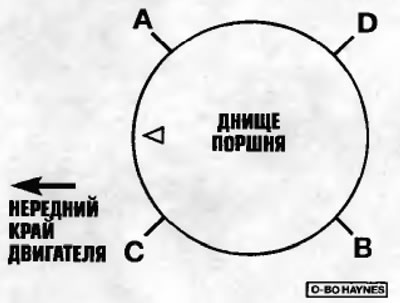
Pic. 10.30 a.m. On four-cylinder engines, position the piston ring locks as shown here before installing the piston and connecting rod assembly
A - The lock of the upper compression ring and the lock of the remote element / expander of the oil scraper ring
B - Second compression ring lock
C - Lock of the upper element of the oil scraper ring
D - The lock of the lower element of the oil scraper ring
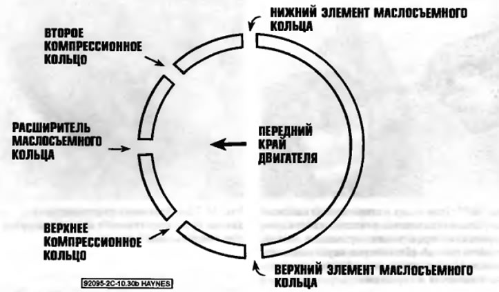
Pic. 10.30 b. On VG engines, position the piston ring locks as shown here before installing the piston and connecting rod assembly
31. Lubricate the piston and rings with clean engine oil and install a piston ring compressor on the piston. To guide the piston into the cylinder, leave a free section of the piston skirt approximately 6 mm long. The rings should be compressed so that they are flush with the piston.
32. Turn the crankshaft so that the crankpin No. 1 is located in the BDC position (bottom dead center), and liberally apply engine oil to the cylinder walls.
33. Positioning the piston so that the markings on its bottom (one or two dots see note in paragraph 18) facing towards the front edge of the engine (to timing belt/chain), carefully insert the piston and connecting rod assembly into cylinder #1 and rest the lower end of the piston ring compressor against the cylinder block.
Note. There is also a mark on the connecting rod that must face the correct direction. On all models, the markings on the connecting rods must face the front edge of the engine (to timing belt/chain).
34. Tap the top edge of the piston ring compressor to bring it into contact with the cylinder block all around.
35. Lightly strike the piston bottom with the end of a wooden or plastic hammer handle (pic. 10.35 am) insert the piston into the cylinder, directing the end of the connecting rod to the crankshaft journal. Just before entering the cylinder, the piston rings may try to pop out of the tool, so continue to hold the tool while inserting the piston. Work slowly, and if you feel any resistance as the piston enters the cylinder, stop immediately. Find the cause of the jam and correct it before continuing. In no case do not insert the piston into the cylinder forcibly, with considerable effort. It is possible to break the ring and/or damage the piston.
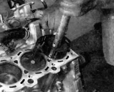
Pic. 10.35. Using a plastic or wooden hammer handle to drive the piston into the cylinder
36. After installing the piston assembly with the connecting rod, check the radial clearance in the connecting rod bearing before final installation of the connecting rod cap.
37. Cut off a piece of thread from the Plastigage kit (kit for measuring clearances in plain bearings) length slightly shorter than the width of the connecting rod bearing, and lay the thread on the crankshaft journal #1, parallel to the axis of the journal (pic. 10.37).
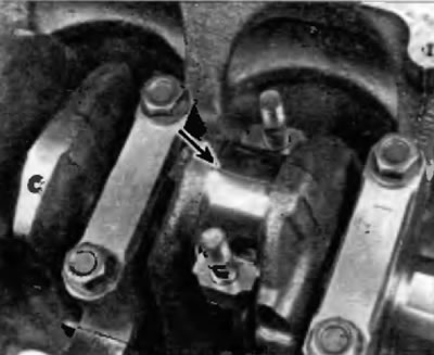
Pic. 10.37. Lay drink Plastigage (from the kit for measuring clearances in plain bearings) pi each connecting rod journal parallel to the center line of the crankshaft
38. Clear a working surface of a cover of the bearing of a rod and establish a cover. Make sure that the alignment mark on the cover is on the same side as the mark on the connecting rod.
39. Screw in the connecting rod bolts and tighten them in two stages to the prescribed torque specified in Specifications at the beginning of this chapter.
Note. To avoid erroneous torque readings that can result if the socket is wedged between the connecting rod cap and the bolt, use a thin wall socket. If the socket is prone to wedging directly between the bolt and the cover, lift it up slightly until contact with the cover is removed. Do not rotate the crankshaft during this operation.
40. Loosen the nuts and remove the connecting rod cap, being very careful not to dislodge the Plastigage thread.
41. To determine the amount of radial clearance, compare the width of the Plastigage dispensing thread with the scale printed on the side of the sleeve bearing clearance kit (pic. 10.41). The radial clearance is usually in the range of 0.025-0.050 mm. Consult your dealer for exact connecting rod bearing clearance on a specific engine.
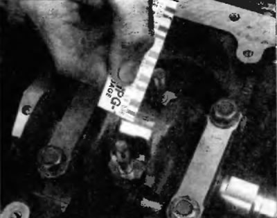
Pic. 10.41. Estimate the radial clearance in the bearing using the scale on the packaging of the plain bearing clearance kit. Measure across the widest part of the Plastigage cast and use the correct scale (imperial and metric scales available)
42. If the clearance is not correct, this may be due to the wrong size of the bearing shells (so you need other inserts). Before deciding on the need to use other liners, make sure that there is no dirt or oil between the liners and the connecting rod or cover at the time of measuring the gap. Check the diameter of the necks again. If one end of the Plestigage is wider than the other, the neck may be tapered. If the clearance still exceeds the prescribed limit, the bearings must be replaced with bearings of reduced oversize.
Warning. When installing a new crankshaft, be sure to use the standard size liners.
Final installation
43. Carefully remove all traces of Plastigage from the crankpin and/or bearing surface. Be very careful not to scratch the bearing by using your fingernail or the edge of a plastic card.
44. Make sure the bearing surfaces are absolutely clean and then apply an even coat of clean molybdenum based grease or engine oil to both bearings. You will need to push the piston into the cylinder to expose the bearing surface in the connecting rod.
45. Slide the connecting rod back onto the journal, install the connecting rod cap and tighten the bolts in two stages to the prescribed torque specified in Specifications at the beginning of this chapter.
46. Repeat the entire procedure for the remaining pistons with connecting rods.
47. Remember the following:
- A) when assembling, keep the back sides of the liners and the inner sides of the connecting rods and caps in absolute frequency;
- 6) carefully monitor the correspondence of the pistons assemblies with connecting rods and cylinders:
- e) the marking on the piston must face the front edge of the engine (to timing belt/chain);
- G) generously lubricate the cylinder walls with clean oil;
- d) after checking the radial clearance when installing the connecting rod caps, lubricate the running surfaces of the bearings.
48. Once the pistons and connecting rods are properly installed, turn the crankshaft by hand a few times to check for obvious binding.
49. And finally, check the axial clearance in the connecting rods again. If it was correct before disassembly and the original crankshaft and «old» connecting rods, it must be correct. If new connecting rods or a new crankset were installed, the end play may not be correct. In this case, remove the connecting rods and contact the service station for their completion.