
Note. The crankshaft can only be removed after the engine has been removed from the vehicle. It is assumed that the faceplate, crankshaft pulley, timing belt/chain, oil pan, oil pump, oil filter, and piston/rod assembly have already been removed. On V6 engines, before starting to remove the crankshaft, remove the crankshaft rear cuff housing by unscrewing the corresponding bolts.
Note. V6 engines have main bearing caps that are secured with four bolts each and side bolts are provided (one on each side), that pass through the cylinder block and screw into the installed main bearing caps.
1. Before removing the crankshaft, measure its axial clearance. Install the dial gauge so that its plunger is aligned with the crankshaft and in contact with the end of the crankshaft (pic. 11.1).
Ryas. 11.1. Checking the axial clearance of the crankshaft using a dial indicator
2. Using a screwdriver, press the crankshaft all the way back and reset the indicator scale. Then press the crankshaft all the way forward and take a reading from the dial indicator. The distance the shaft moves is the axial clearance. A typical crankshaft axial clearance falls within the range of 0.075-0.250 mm. If the clearance exceeds this value, check the thrust surfaces of the crankshaft after removing it for wear. If no wear is found, installing new main bearings should allow clearance to be corrected.
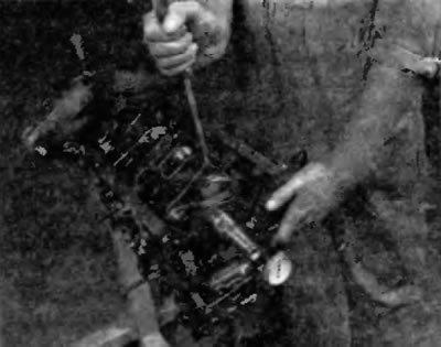
3. If there is no dial indicator, feelers can be used. Gently press the crankshaft against the stop towards the front end of the engine. To determine the clearance, insert a feeler gauge between the crankshaft and the front side of the thrust bearing or washer (pic. 11.3). Adjust the thickness of the probe so that it slides in tight.
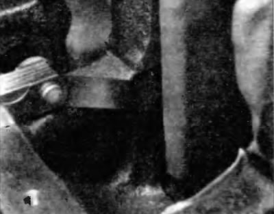
Pic. 11.3. Checking the axial clearance of the crankshaft using a feeler gauge in the journal of the thrust bearing
4. Loosen the main bearing cap bolts, loosening each one ¼ turn at a time and ensuring that they can be turned out by hand (rice. 11.19, a). On V6 engines, first remove the side bolts (in the prescribed sequence) (rice. 11.19, in), and then internal bolts (rice. 11.19, b).
5. Gently tap the main bearing caps with a soft-faced hammer. Pull the main bearing cap straight up and off the cylinder block. Take care not to drop the bearing shells if they are removed with the cover.
6. Carefully remove the crankshaft from the engine. It is recommended to involve an assistant in this, since the crankshaft is quite heavy and bulky. With the bearing shells in place in the cylinder block and main bearing caps, install the main bearing caps on the cylinder block and hand-tighten the bolts. The main bearing caps should be installed with the arrow pointing towards the front of the engine.