
Table of check of the relay of an automatic mode of window regulators.
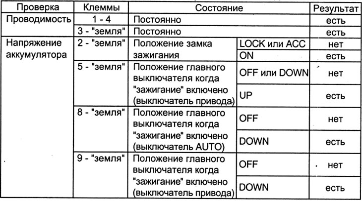
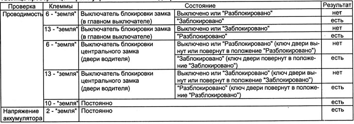
Table for checking the relay control circuit of the door locks.
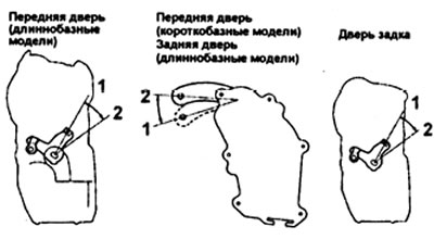
Checking switches
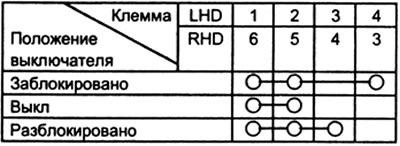
1. Checking the switch.
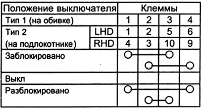
A) Check the conductivity of the switch circuits according to the table.
b) Replace the switch if the continuity of the circuits is broken.
Long wheelbase models
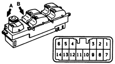
A - locked, B - unlocked
Short wheelbase models
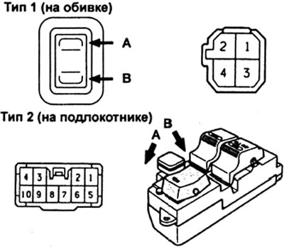
A - locked, B - unlocked.
2. Checking the central locking switch.
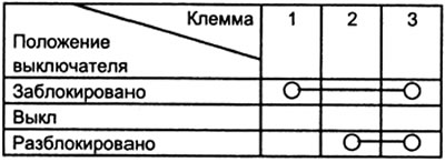
A) Check the conductivity of the switch circuits according to the table.
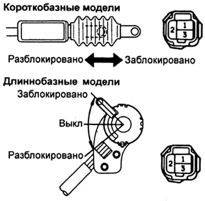
b) Replace the switch if the continuity of the circuits is broken.
Checking the electric drive of the door lock
1. Checking the operation of the electric drive.
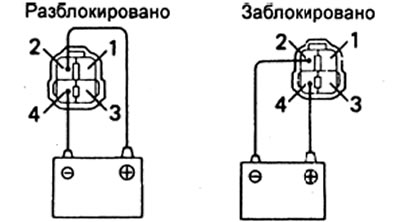
A - locked, B - unlocked
A) Connect the battery to terminals 2 (+) and 4 (-): the latch of the lock must move to the position "unlocked".
b) Reverse the polarity of the battery connection: the door latch should move to the position "blocked".
V) Replace the drive if it does not work as specified.
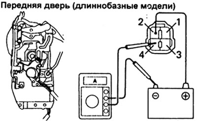
2. Checking the operation of the PTC thermistor.
Note: The front door thermistor operation test is shown below, the thermistor operation test for other doors is the same.
A) Connect "plus" battery to terminal 2 of the connector.
b) Connect "plus" ammeter to terminal 4 of the connector, and "minus" - To "minus" battery. The current should change from about 3.2A to about 0.5A within 10-60 seconds (for short wheelbase models: within 20 - 70 seconds).
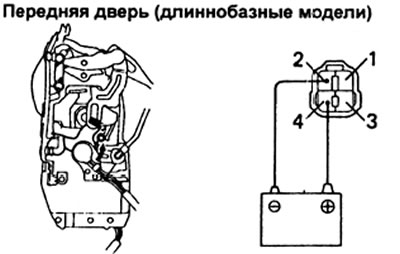
V) Disconnect all wires.
G) After about 60 seconds, connect "plus" battery to terminal 4, and "minus" - to terminal 2 of the connector. The door lock should move to the position "blocked".
Checking the door lock control relay
1. Checking the relay circuit.
A) Disconnect the connector from the relay.
b) Check the connector on the wire side according to the table.
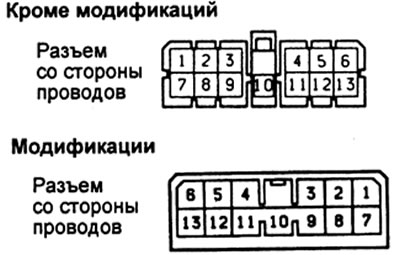
V) If all circuits are normal, check the door lock signal.
G) If the circuit parameters do not match those given in the table, then check other circuits and systems.
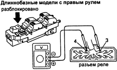
2. Checking the door lock signal,
A) Connect the connector to the relay.
b) Connect "plus" voltmeter to terminal 3, "minus" voltmeter - to terminal 4 of the connector on the wire side.
V) Move the central locking switch to the position "unlocked": The voltage should increase from 0 V to battery voltage in about 0.2 seconds.
G) Reverse the polarity of the voltmeter connection.
d) Move the central locking switch to the position "blocked": The voltage should increase from 0V to battery voltage in about 0.2 second.
e) Replace the relay if test results are negative.