Share information:

Vehicle cooling and heating Toyota Land Cruiser 60/80

Cooling, heating systems — design description
Engine cooling system 1. damper body; 2. To the radiator; 3. Outlet pipe; 4. To the radiator; 5. Bypass pipe; 6. Pump; 7. From the radiator; 8. Inlet pipe; 9. From the heater; 10. To the heater Cooling system...
Engine cooling system 1. damper body; 2. To the radiator; 3. Outlet pipe; 4. To the radiator; 5. Bypass pipe; 6. Pump; 7. From the radiator; 8. Inlet pipe; 9. From the heater; 10. To the heater Cooling system...

Specifications of the cooling and heating system
Radiator Plug Valve Setting Pressure 0.6 - 1.0 bar Thermostat opening temperature 83 - 95°C Type of refrigerant in the air conditioning system: – until 1993 inclusive R12 – since 1994 R134 A Refrigerant charge 795 - 910...
Radiator Plug Valve Setting Pressure 0.6 - 1.0 bar Thermostat opening temperature 83 - 95°C Type of refrigerant in the air conditioning system: – until 1993 inclusive R12 – since 1994 R134 A Refrigerant charge 795 - 910...

Antifreeze — general information
A mixture of antifreeze and water is poured into the cooling system in a ratio of 50/50 to 70/30. The concentration of antifreeze is checked with a hydrometer.
A mixture of antifreeze and water is poured into the cooling system in a ratio of 50/50 to 70/30. The concentration of antifreeze is checked with a hydrometer.

Thermostat — check and replacement
Engine thermostat 1FZ-FE 1. Thermostat 2. Gasket 3. Inlet pipe Warning! Work is carried out on a cold engine in compliance with safety measures (antifreeze is poisonous). Examination 1. Before drawing a conclusion about...
Engine thermostat 1FZ-FE 1. Thermostat 2. Gasket 3. Inlet pipe Warning! Work is carried out on a cold engine in compliance with safety measures (antifreeze is poisonous). Examination 1. Before drawing a conclusion about...

Fan impeller and fluid coupling — removal and inspection
Examination 1. If cracks are found on the blades or impeller play on the shaft, replace the impeller. 2. Replace the coupling if a leak is found. 3. The coupling must be replaced if axial play of the impeller on the...
Examination 1. If cracks are found on the blades or impeller play on the shaft, replace the impeller. 2. Replace the coupling if a leak is found. 3. The coupling must be replaced if axial play of the impeller on the...

Radiator and expansion tank — removal and installation
Radiator and related parts 1. Bypass hose; 2, 20. Radiator hose; 3. Battery fastening bracket; 4. Battery; 5. Tray; 6. Casing; 7. Impeller and clutch; 8. Front grill; 9, 13. Bracket; 10. Drain valve; 11. Gasket; 12....
Radiator and related parts 1. Bypass hose; 2, 20. Radiator hose; 3. Battery fastening bracket; 4. Battery; 5. Tray; 6. Casing; 7. Impeller and clutch; 8. Front grill; 9, 13. Bracket; 10. Drain valve; 11. Gasket; 12....

Oil cooler — removal and installation
Engine oil cooler 3F-E 1, 4. Gasket; 2. Pressure reducing valve; 3. Spring; 5. Plug; 6, 11. Coolant hose; 7. Oil cooler; 8. Ring; 9. Oil pressure sensor; 10. Bracket; 12. Oil filter Engine oil cooler 1FZ-FE 1. Gasket;...
Engine oil cooler 3F-E 1, 4. Gasket; 2. Pressure reducing valve; 3. Spring; 5. Plug; 6, 11. Coolant hose; 7. Oil cooler; 8. Ring; 9. Oil pressure sensor; 10. Bracket; 12. Oil filter Engine oil cooler 1FZ-FE 1. Gasket;...

Coolant pump — removal, inspection and installation
Engine coolant pump 3F-E 1. Bypass hose; 2. Oil cooler hose; 3. Gasket; 4. Pump; 5. Pulley flange; 6. Drive belt; 7. Fluid coupling; 8. Impeller; 9. Pulley; 10. Inlet hose; 11. Pump plate; 12. Heater hose Engine coolant...
Engine coolant pump 3F-E 1. Bypass hose; 2. Oil cooler hose; 3. Gasket; 4. Pump; 5. Pulley flange; 6. Drive belt; 7. Fluid coupling; 8. Impeller; 9. Pulley; 10. Inlet hose; 11. Pump plate; 12. Heater hose Engine coolant...

Fluid temperature sensor — check and replace
Location of the temperature sensor on the 3F-E engine 1. Wiper motor; 2. Brake fluid level sensor; 3. Headlight cleaner motor; 4. Fluid temperature sensors; 5. Oil pressure sensor Location of the temperature sensor on...
Location of the temperature sensor on the 3F-E engine 1. Wiper motor; 2. Brake fluid level sensor; 3. Headlight cleaner motor; 4. Fluid temperature sensors; 5. Oil pressure sensor Location of the temperature sensor on...

Heater fan motor and circuit
Cabin air conditioning wiring diagram 1. Battery; 2. Main fuse; 3. Additional fuse; 4. Ignition switch; 5. Heater relay; 6. Electric motor; 7. Resistor; 8. Motor relay; 9. Fan switch; 10. Air conditioner switch; 11. To...
Cabin air conditioning wiring diagram 1. Battery; 2. Main fuse; 3. Additional fuse; 4. Ignition switch; 5. Heater relay; 6. Electric motor; 7. Resistor; 8. Motor relay; 9. Fan switch; 10. Air conditioner switch; 11. To...

Heater radiator — removal and installation
The procedure for removing the heater core is described in detail below. It is much easier to remove the radiator after removing the evaporator, however, to do this, you must first depressurize the air conditioning...
The procedure for removing the heater core is described in detail below. It is much easier to remove the radiator after removing the evaporator, however, to do this, you must first depressurize the air conditioning...
Heating and air conditioning control panel
Attention! Early production vehicles are equipped with cable-operated interior heating/air conditioning. On cars of later releases, an electric drive is installed with air intake dampers. Removal and installation 1....
Attention! Early production vehicles are equipped with cable-operated interior heating/air conditioning. On cars of later releases, an electric drive is installed with air intake dampers. Removal and installation 1....
Control cable adjustment
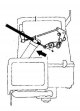
After fixing the cables on the control panel and after mounting the control panel itself, it is necessary to adjust the tension of the cables. 1. Move the control handles to the RECIRC, COOL and DEF positions. 2. To...
After fixing the cables on the control panel and after mounting the control panel itself, it is necessary to adjust the tension of the cables. 1. Move the control handles to the RECIRC, COOL and DEF positions. 2. To...

Checking the heater/air conditioner controls
Checking the A/C Switch on 80 Series Vehicles 1. Connector A 2. Connector B 62 Series Heater Switch Test Table 62 Series Rear Heater Switch Check Chart 1. Remove the air conditioner switch and check the contact closure...
Checking the A/C Switch on 80 Series Vehicles 1. Connector A 2. Connector B 62 Series Heater Switch Test Table 62 Series Rear Heater Switch Check Chart 1. Remove the air conditioner switch and check the contact closure...

Air conditioning and heating systems
The main units of the air conditioning system 1. Pressure switch; 2. Capacitor; 3. Compressor; 4. Dehumidifier Attention! The air conditioning system is under high pressure. Until the complete removal of the...
The main units of the air conditioning system 1. Pressure switch; 2. Capacitor; 3. Compressor; 4. Dehumidifier Attention! The air conditioning system is under high pressure. Until the complete removal of the...

Air conditioner dehumidifier — removal and installation
Refrigerant line pipes on water separator on 60, 62 and 80 series vehicles 1, 3. Liquid hose; 2. Dehumidifier Removal and installation Attention! Depressurization of the air conditioner line and refrigerant filling is...
Refrigerant line pipes on water separator on 60, 62 and 80 series vehicles 1, 3. Liquid hose; 2. Dehumidifier Removal and installation Attention! Depressurization of the air conditioner line and refrigerant filling is...

Air conditioning compressor — removal and installation
Compressor mounting details 1. Bracket Removal and installation 1. Depressurize the air conditioner and remove the refrigerant in a car service. 2. Disconnect the battery from the ground. 3. Remove the belt from the...
Compressor mounting details 1. Bracket Removal and installation 1. Depressurize the air conditioner and remove the refrigerant in a car service. 2. Disconnect the battery from the ground. 3. Remove the belt from the...

Air conditioner condenser — removal and installation
Capacitor mounting bolts 1. Drain hose; 2. Bracket of the lock of a cowl; 3. Liquid refrigerant pipe; 4. Clamp Removal and installation 1. Depressurize the air conditioner and remove the refrigerant in a car service. 2....
Capacitor mounting bolts 1. Drain hose; 2. Bracket of the lock of a cowl; 3. Liquid refrigerant pipe; 4. Clamp Removal and installation 1. Depressurize the air conditioner and remove the refrigerant in a car service. 2....

Evaporator and expansion valve
Mounting the evaporator on cars series 60, 62 Mounting the evaporator on 80 series vehicles 60, 62 series car evaporator parts 1. Wires; 2. Clutch relay; 3. Holder; 4. Thermistor; 5. Expansion valve; 6. Liquid...
Mounting the evaporator on cars series 60, 62 Mounting the evaporator on 80 series vehicles 60, 62 series car evaporator parts 1. Wires; 2. Clutch relay; 3. Holder; 4. Thermistor; 5. Expansion valve; 6. Liquid...
This section is available on: russian, bulgarian, belarusian, ukrainian, serbian, croatian, romanian, polish, slovak, hungarian
Similar sections for other Toyota models
➥ Power unit: Cooling and lubrication system Toyota Camry Vista V40 (1994-1998)
➥ Power unit: Cooling system Toyota Corolla Verso 3 (2004-2009)
➥ Power unit: Cooling system Toyota Corona T190 (1992-1997)
➥ Power unit: Cooling system Toyota Carina T190 (1992-1996)
➥ Power unit: Cooling and heating Toyota Highlander 1 (2000-2007, petrol)
➥ Power unit: Cooling and heating Toyota 4Runner N120 (1989-1995)
➥ Power unit: Cooling and air conditioning Toyota RAV 4 XA10 (1994-2000)
➥ Gasoline engines «Y»: Cooling and lubrication system Toyota Dyna Y50/Y60 (1984-1995)
Link in different formats to this article
TEXTHTMLBB Code
- General information
- Introduction to the guide
- Controls and instruments
- Maintenance
- Power unit
- Petrol engines
- Diesel engines
- Cooling and heating
- Power and exhaust systems
- Engine electrical equipment
- Engine management systems
- Transmission
- Automatic gearbox
- Transmission line
- Chassis, running gear
- Brake system
- Car suspension
- Steering
- Body and interior
- Exterior (external elements)
- Interior (internal elements)
- Doors, locks and windows
- Electrical equipment
- Equipment and devices
- Electrical circuits
- General information
- User manual
- Maintenance
- Power unit
- Petrol engines 2F and 3F-E
- Petrol engines 1FZ-FE
- Engine overhaul
- Engine electrical equipment
- Cooling and heating
- Fuel system (carburetor)
- Fuel system (injector)
- Toxicity reduction system
- Transmission
- Car gearbox
- Clutch
- Transfer case
- Drive shafts and axles
- Chassis, running gear
- Brake system
- Car suspension
- Steering
- Body and interior
- Exterior and interior
- Doors, locks and windows
- Electrical equipment
- Equipment and devices
- Electrical circuits
- General information
- User manual
- Maintenance
- Power unit
- Engine adjustment
- Engine repair
- Fuel system
- Control system
- Turbocharging system
- Cooling and lubrication system
- Charge and start system
- Transmission
- Clutch
- Mechanical gearbox
- Automatic gearbox
- Transfer case
- Chassis, running gear
- Car suspension
- Brake system
- Steering
- Body and interior
- Body elements
- Heating and air conditioning
- Electrical equipment
- Equipment and devices
- Electrical circuits