
Example of a standard wiring diagram
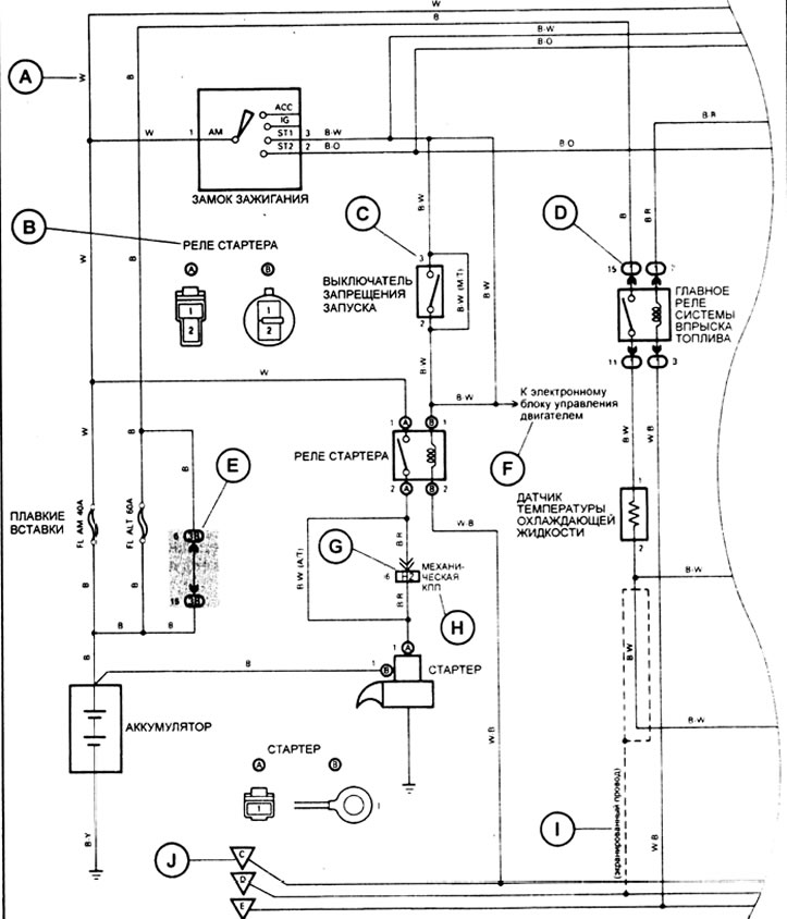
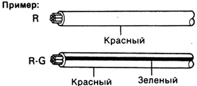
A: In the diagrams, the color of the wire is indicated by a letter code (see picture):
| Code | Color | Code | Color |
| IN | black | ABOUT | orange |
| BR | brown | R | pink |
| G | green | R | red |
| GR | grey | V | violet |
| L | blue | W | white |
| LG | light green | Y | yellow |
Note: with a two-letter code (e.g. RG) the first letter indicates the main color of the wire (red), and the second - the color of the strip on the wire (green).
B: Indicates the connector connected to this item (the number indicates the terminal number of the connector).
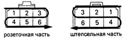
C: Indicates the terminal No. of the connector. The numbering system is different for the female and plug parts of the connector.
- The pins in the female connector are numbered from top left to bottom right.
- The pins in the male part of the connector are numbered from top right to bottom left.
Note: when multiple connectors are used in one node, the names of each connector are indicated (letter of the alphabet) and contact number. The numbering system for the common wiring diagram is the same as above.
D: Indicates a relay block. Shading is not applied, only the number of the relay block is shown, which distinguishes it from the junction box of the block.
Example:
E: Indicates distribution block (the number in the circle indicates the distribution block number, and the connector code is indicated next to it).
F: Indicates the system that has communication with the system in question.
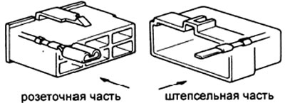
G: Indicates the wiring harness and wiring harness connector.
- Wire harness with plug lug marked with arrows (
- The numbers on the outside correspond to the terminal numbers of the connector.
- All connectors are shown with the opening side so that the lock is at the top.
H: () used to specify different wires and connectors, such as vehicle model, engine type, or specification.
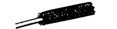
I: Indicates shielded wiring harness see figure.
J: Indicates the ground point.
| Code | Location |
| EA | on the right front fender |
| EV | on the left front fender |
| EU | on the engine block |
| ED | left front radiator |
| IE | on the left protective panel |
| IF | on the right protective panel |
| IG | under the left protective panel |
| VN | inside, on the bottom rear panel |
Connectors
Connectors are divided into groups according to their location on the vehicle and have a two-letter designation. The first letter indicates the group to which the connector belongs.
| Group | Location |
| E | engine compartment |
| I | dashboard area |
| IN | body |
When disconnecting the connectors, do not pull on the wires and be careful when disconnecting the retainer clips.
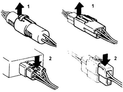
1 - Press, 2 - Press.