
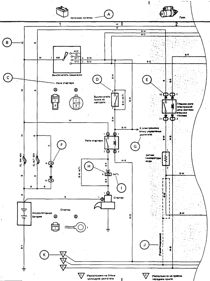
A: The name of the system.
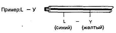
B: Indicates the wire color code.
| B - black | O - orange |
| BR - brown | P - pink |
| G - green | R - red |
| GR - gray | V - purple |
| L - blue | W - white |
| LG - light green | Y - yellow |
The first letter indicates the base color of the wire, and the second letter indicates the color of the strip.
C: Indicates the connector connected to the part (number indicates output number).
D: Indicates the pin number of the connector.
The numbering system is different for the female and plug parts of the connector.
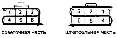
The numbering system for the common wiring diagram is the same as above.
E: Indicates a relay block. Shading is not applied, only the number of the relay block is shown, which distinguishes it from the jumper block.
Example: 1 indicates relay block #1.
F: Jumper block (The number in the circle indicates the number of the jumper block, and next to it is the connector code).
G: Indicates a system that has a relationship with the one under consideration.
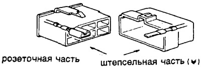
H: Indicates the wiring harness and wiring harness connector. The wiring harness with plug-in terminal is marked with arrows.
The numbers on the outside correspond to the pin numbers.
All connectors are shown with the open side so that the lock is at the top.
I: () used to specify different wires and connectors, such as vehicle model, engine type, or specification.
J: Indicates insulated wiring harness.
K: Indicates the ground connection point.
Conventions
Manual - manual transmission.
Automatic transmission - automatic transmission.
2L - 2L engine.
1Y, 2Y, 3Y - 1Y, 2Y, 3Y motors.
150 — Dyna 150.
100 — Dyna 100.