Removing the cylinder head
1. Disconnect the negative plug from the storage battery.
2. Drain the coolant from the cylinder block and radiator.
3. Disconnect cables, remove an arm of fastening of cables of management, having turned away two bolts.
Note: before disconnecting the automatic transmission control cable, mark with a marker (or measure with a caliper) its adjustment (nuts position).
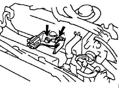
4. Remove the generator.
- A) Disconnect the wire harness clamp from the clamp on the alternator.
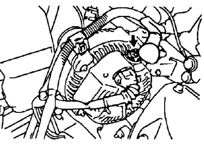
- b) Disconnect the generator connector.
- V) Remove the rubber cap and unscrew the wire fastening nut, disconnect the generator wire.
- G) Loosen the lock bolt (models with air conditioning), adjusting bolt and hinge bolt.
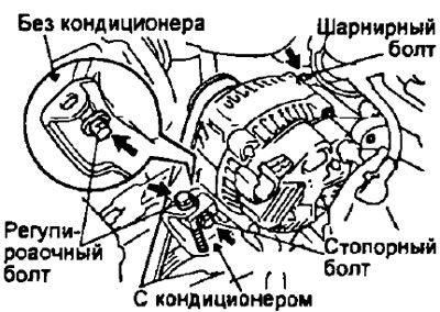
- d) Remove the alternator drive belt
- e) Remove the adjustment stop bolt (models with air conditioning) or adjusting bolt (models without air conditioning) and hinge bolt.
- and) Remove the generator.
5. Remove the distributor.
- A) Disconnect the two distributor connectors.
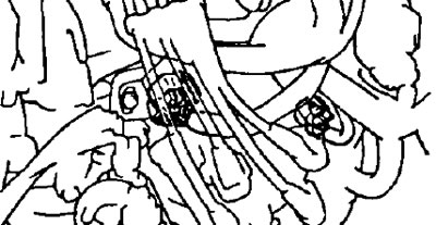
- b) Disconnect the high voltage wires at the rubber caps. Do not pull on wires.
Note: Straining or bending the wires may cause internal damage.
- V) Turn away two bolts and remove the distributor.
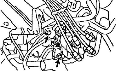
5. Remove the exhaust manifold.
- A) Remove the five bolts and remove the top heat shield.
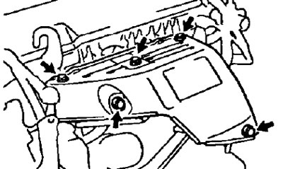
- b) Turn away bolts, nuts and remove an exhaust manifold bracket and a reception pipe.
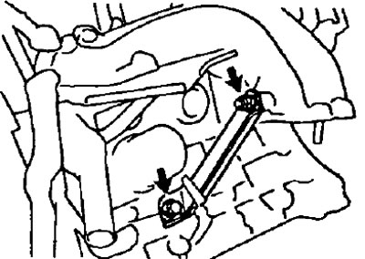
- V) Loosen the six nuts, remove the exhaust manifold and gasket.
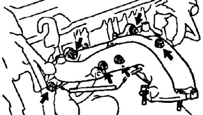
- G) Remove the three bolts and remove the lower heat shield.
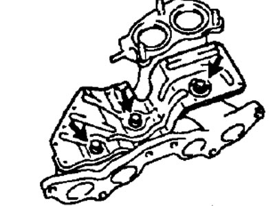
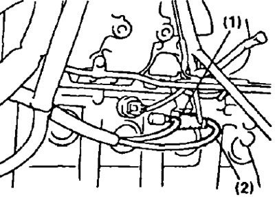
6. Remove the coolant outlet fitting.
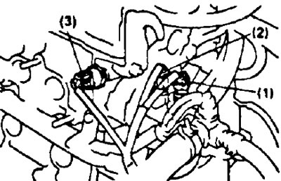
- A) Disconnect the following connectors:
- (1) Coolant temperature gauge sensor connector
- (2) Coolant temperature sensor connector.
- (3) Oil pressure sensor connector.
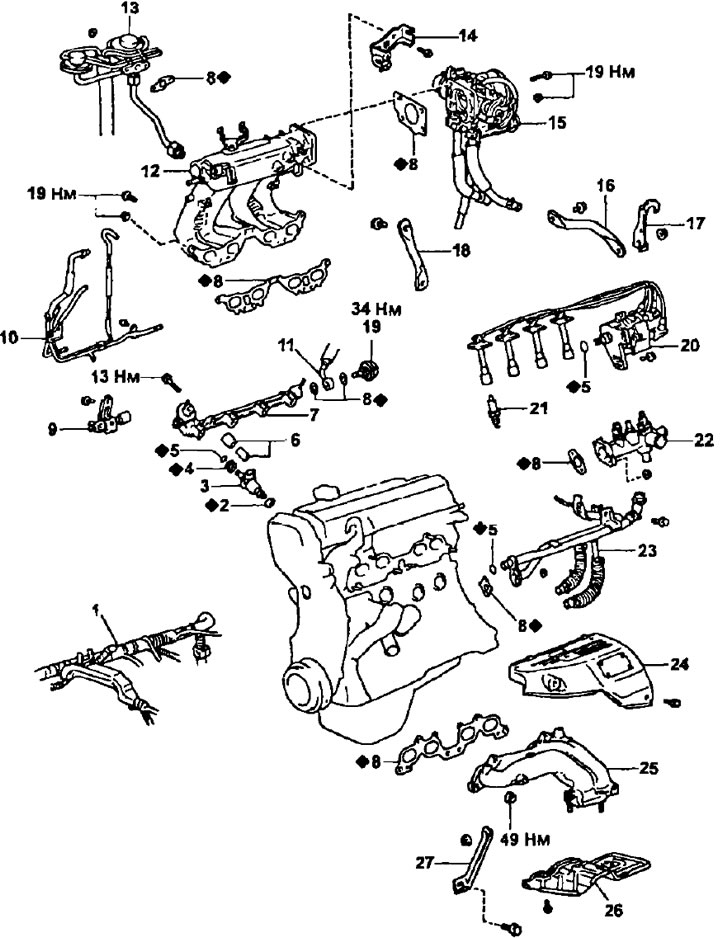
Removal and installation of a head of the block of cylinders. 1 - engine wiring harness, 2 - insulator, 3 - injector, 4 - sealing sleeve, 5 - O-ring seal, 6 - spacer, 7 - fuel manifold, 8 - gasket, 9 - EGR valve (models with exhaust gas recirculation), 10 - vacuum tube, 11 - fuel supply hose, 12 - intake chamber assembly with manifold, 13 - EGR valve and vacuum modulator (models with exhaust gas recirculation), 14 - throttle cable bracket, 15 - throttle body, 16 - intake manifold bracket No. 2, 17 - left engine lifting hook, 18 - intake manifold bracket No. 1, 19 - fuel pressure pulsation damper, 20 - distributor, 21 - spark plug, 22 - coolant outlet, 23 - coolant bypass pipe, 24 - upper heat shield, 25 - exhaust manifold, 26 - lower heat shield, 27 - exhaust manifold bracket.
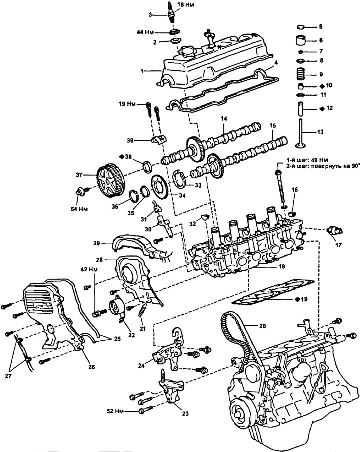
Dismantling of a head of the block of cylinders. 1 - cylinder head cover, 2 - spark plug tube seal, 3 - spark plug, 4 - gasket, 5 - adjusting washer, 6 - tappet, 7 - crackers, 8 - valve spring plate, 9 - valve spring, 10 - oil scraper cap, 11 - spring seat, 12 - valve guide, 13 - valve, 14 - intake camshaft, 15 - exhaust camshaft, 16 - segment plug, 17 - oil pressure sensor, 18 - cylinder head, 19 - gasket cylinder heads, 20 - timing belt, 21 - tension roller spring, 22 - tension roller, 23 - right engine mount, 24 - generator bracket and right engine lift bracket, 25 - gasket, 26 - timing belt cover No. 2, 27 - clamps, 28 - timing belt cover #3, 29 - wire harness guard, 30 - camshaft position sensor, 31 - camshaft position sensor connector, 32 - segment plug, 33 - circlip, 34 - camshaft auxiliary gear exhaust valve shaft, 35 - spring washer, 36 - circlip, 37 - camshaft pulley, 38 - camshaft oil seal, 39 - camshaft bearing cap.
Note: Mark all hoses with paint prior to removal for proper installation.
- b) Disconnect the following hoses:
Note: Mark all hoses with paint prior to removal for proper installation
- (1) Upper radiator hose;
- (2) coolant bypass hose;
- (3) heater hose;
- (4) Coolant supply hose to idle control valve;
- (5) Two evaporative emission hoses (if installed).
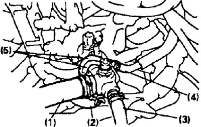
- V) Unscrew the two nuts, remove the coolant outlet pipe and the gasket.
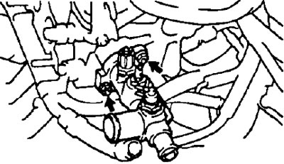
7. Remove the coolant bypass tube.
- A) Disconnect the following hoses:
- (1) Idle air control valve coolant bypass hose from the coolant bypass pipe.
- (2) Heater hose from coolant bypass pipe.
- (3) (Models with oil cooler) Two coolant bypass hoses from the oil cooler.
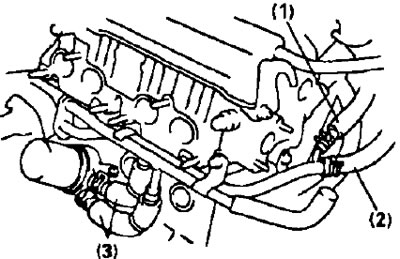
- b) Remove two bolts and two nuts.
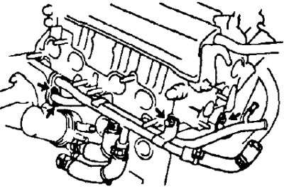
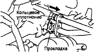
- V) Disconnect the coolant bypass pipe from the coolant pump cover and remove it.
- G) Remove the gasket and O-ring.
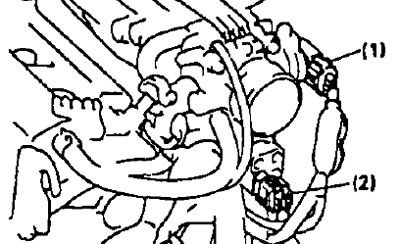
8. Remove the throttle body.
- A) Disconnect the following connectors:
- (1) Throttle position sensor connector.
- (2) Idle air control valve connector.
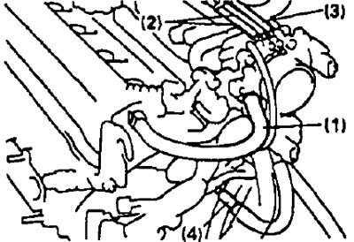
- b) Disconnect the following hoses:
- (1) Crankcase ventilation hose from throttle body.
- (2) (Models with exhaust gas recirculation system) Two vacuum hoses from the throttle body.
- (3) (Models with evaporative emission system) Vacuum hose from throttle body.
- (4) Vacuum hose from tube.
- V) Remove four bolts or two bolts and two nuts.
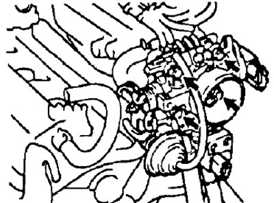
- d) Remove the throttle body and gasket.
9. Remove the left engine lifting hook and intake manifold bracket #2 by removing the bolt and nut.
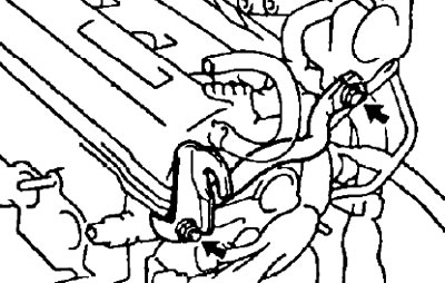
10. (Models with exhaust gas recirculation) Remove the EGR valve and vacuum modulator.
- A) Disconnect the following hoses:
Note: Mark all hoses with paint prior to removal for proper installation.
- (1) Vacuum hose from channel "E* electropneumatic valve of the exhaust gas recirculation system.
- (2) Vacuum hose from channel *G* of the electro-pneumatic valve of the exhaust gas recirculation system.
- b) Loosen the union nut of the exhaust gas recirculation pipe. unscrew the two nuts and remove the EGR valve, vacuum modulator, vacuum hoses and gasket.
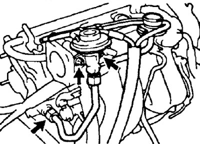
11. Remove the intake manifold bracket No. 1 by unscrewing 2 bolts.
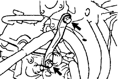
12. Disconnect the following connectors and wire:
- (1) knock sensor connector;
- (2) (Models with exhaust gas recirculation) connector for the electropneumatic valve of the exhaust gas recirculation system;
- (3) the wire "masses".
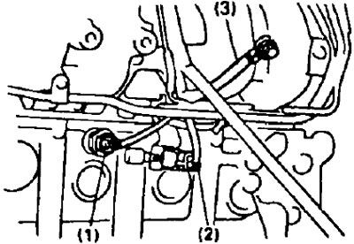
13. Remove the vacuum tube.
Note: Mark all hoses and tubes with paint before removing for proper installation.
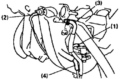
- A) Disconnect the following hoses:
- (1) vacuum hose from the fuel pressure regulator.
- (2) vacuum hose from the gas filter.
- (3) air hose for the air bypass control valve of the power steering pump from the intake manifold.
- (4) the air hose of the idle speed increase valve when the air conditioner is turned on from the vacuum tube.
- (5) two vacuum hoses of the air bypass control valve of the power steering pump from the air tube.
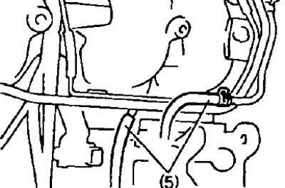
- b) Remove the two bolts and the vacuum tube.
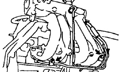
14. Disconnect the fuel supply hose from the fuel manifold after depressurizing the gas tank.
- A) Disconnect the engine wiring harness clamp from the bracket.
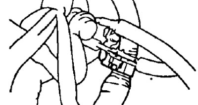
- b) Using the special tool, loosen the fuel pressure pulsation damper.
- V) Remove the fuel pressure pulsation damper and two gaskets and disconnect the fuel supply hose from the fuel rail.
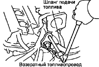
15. Disconnect the fuel return hose from the fuel return line.
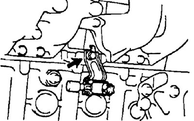
16. (Models with exhaust gas recirculation) Remove the electro-pneumatic valve of the exhaust gas recirculation system by unscrewing the bolt.
17. Remove the intake manifold.
- A) Disconnect the following hoses, having previously marked them:
- (1) crankcase ventilation hose from the intake manifold.
- (2) vacuum hose for the idle speed increase valve when the air conditioner is turned on from the intake manifold.
- (3) intake manifold absolute pressure sensor vacuum hose from the gas filter.
- (4) brake booster vacuum hose from the intake manifold.
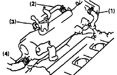
- b) Disconnect the two engine harness guard clips from the #2 timing belt cover bolts in the sequence shown.
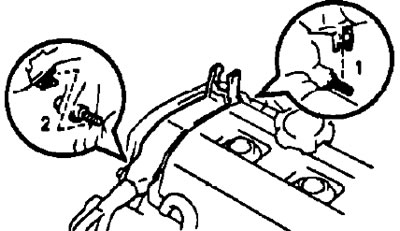
- V) Disconnect the two engine harness clips from the mounting bracket on the intake manifold.
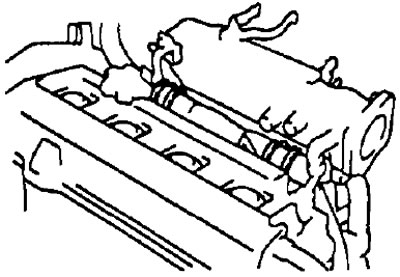
- G) Remove six bolts, two nuts and remove the intake manifold and gasket.
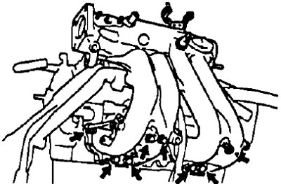
18. Remove the fuel manifold and injectors.
- A) Disconnect the injector connectors.
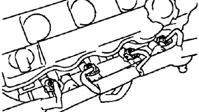
- b) Remove the two bolts and remove the fuel manifold with injectors.
Note: Be careful not to drop the injectors when removing the fuel manifold.
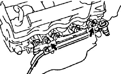
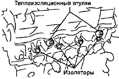
- V) Remove insulators and two heat-insulating plugs from a head of the block of cylinders.
- G) Remove the injectors from the fuel manifold.
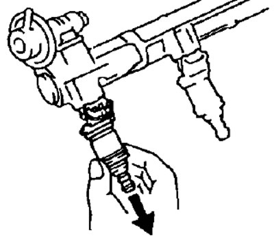
- d) Remove the O-ring and seal from each injector if you are replacing them with new ones during installation.
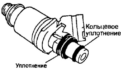
19. Remove the timing belt from the camshaft sprocket.
- A) Remove the #2 timing belt cover by unscrewing the 5 bolts and remove the two spacers.
- b) Loosen the idler pulley mounting bolt and press the pulley to the left, being careful not to damage the belt surface, and tighten the bolt.
- V) Remove the timing belt from the pulley
- G) Cover the opening with a rag (under cover #1), so nothing gets in there.
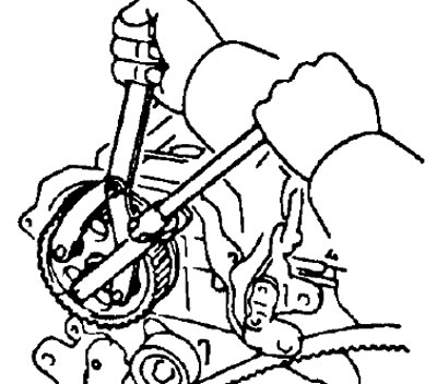
20. Having unscrewed a bolt, remove a gear pulley of a camshaft by means of a special tool.
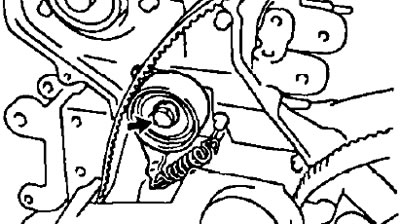
21. Remove the tension roller and spring by unscrewing the bolt.
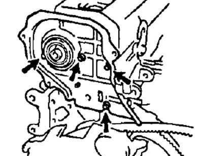
22. Remove cover No. 3 of the timing belt by unscrewing the four bolts.
Note:
- Hold the timing belt so that the crankshaft sprocket and belt do not move.
- Be careful not to drop anything inside the timing belt cover.
- Keep the belt away from oil, water or dust.
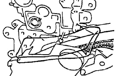
23. Remove the alternator bracket and the right engine lifting hook by removing the three bolts.
24 Remove the oil pressure switch.
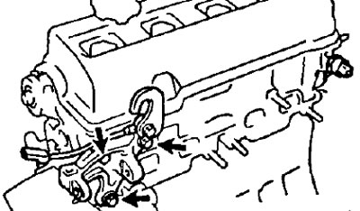
25. Turn away four nuts, remove consolidation of tubes of spark plugs, a cover of a head of the block of cylinders and a lining.
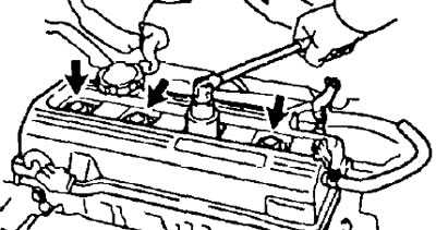
Note: Arrange the spark plug tube seals in the order of removal to install them correctly to minimize the possibility of oil leakage.
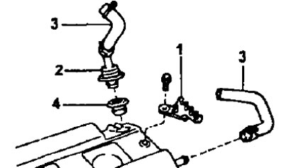
26. Remove the high-voltage wire clamps, crankcase ventilation valve and hose from the cylinder head cover.
- A) Turn away a bolt and remove clips of high-voltage wires (1).
- b) Remove the crankcase ventilation valve (2), hose (3) and seal (4).
- V) Remove the crankcase ventilation hose (3).
27. Remove the intake and exhaust camshafts.
Note: Since the camshaft end play is very small, to prevent jamming and/or damage to the camshaft, it is necessary to keep the camshaft in a horizontal position when removing it, for this it is necessary to follow the dismantling procedure below.
- A) Turn the camshaft 2-3 turns with a wrench, first turn the crankshaft so that the pistons are in the middle position. Put paint marks on the crankshaft pulley for subsequent installation.
- b) Locate the alignment marks on the gears and mark them with a marker.
- V) Install the camshafts in their original position and measure the thermal clearances in the valves so that they can be immediately adjusted during assembly.
27.1. Remove the exhaust camshaft.
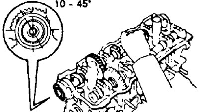
- A) Install the intake camshaft so that the hole for the technological bolt of the intake camshaft gears is 10-45°before installing in V MT, as shown in the figure.
Note: In this position, the lobes on the exhaust camshafts of cylinders #2 and #4 act on the valve lifters.
- 6) Attach the exhaust camshaft sub gear to the main gear with a service bolt.
Recommended process bolt:
- thread diameter - 6 mm
- thread pitch - 1.0 mm
- bolt length - 16-20 mm
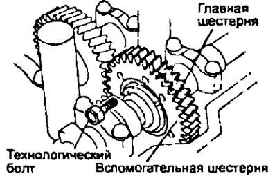
Note: When removing the camshaft, make sure that this operation neutralizes the torsional force of the auxiliary gear plate washer.
- V) Remove the two bolts and remove the rear bearing cover.
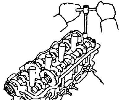
- G) Evenly loosen and remove the 6 bearing cap bolts #1, #2 and #4 in several passes in the sequence shown.
Note: do not loosen the #3 bearing cap bolts in this operation.
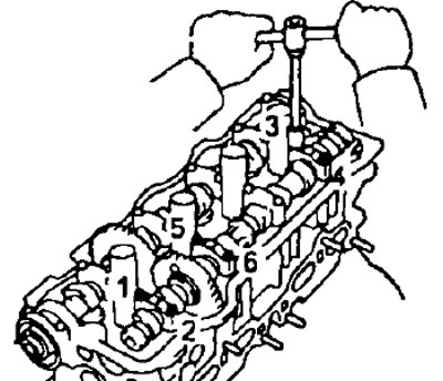
- d) Remove bearing caps #1, #2 and #4.
- e) Loosen and remove the two #3 bearing cap bolts one by one.
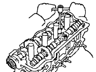
- and) Remove bearing cap N83 and exhaust camshaft
Note:
- If the camshaft does not rise straight and horizontal, retighten the No. 3 bearing cap bolts and follow the steps to install the bearing caps and dowel pin. Then do the operations to remove the exhaust camshaft again.
- Do not use a special tool to remove the camshaft.
27.2. Remove the intake camshaft.
- A) Set the inlet camshaft locating pin at 80-115°until it is at TDC.
Note: In this position, the lobes on the intake camshafts of cylinders #1 and #3 act on the valve lifters.
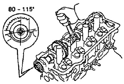
- 6) Turn away two bolts, remove a cover of the forward bearing and an epiploon.
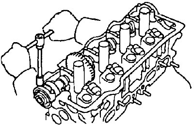
- V) Evenly loosen and remove the 6 bearing cap bolts #1, #3 and #4 in several passes in the sequence shown.
Note: do not loosen the #2 bearing cap bolts in this operation.
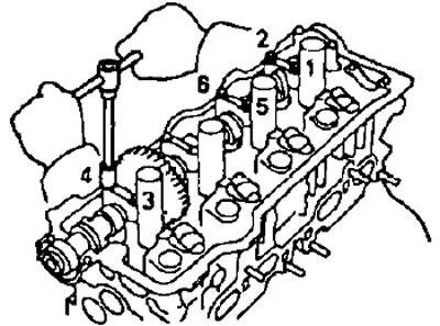
- G) Remove bearing caps #1, #3 and #4.
- d) Loosen and remove the two #2 bearing cap bolts one by one
- e) Remove bearing cap #2 and camshaft.
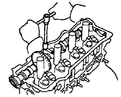
Note:
- If the camshaft does not rise straight and horizontal, retighten the No. 2 bearing cap bolts and follow the steps to install the bearing caps and dowel pin. Then do the operations to remove the camshaft again.
- Do not use a special tool to remove the camshaft.
28. If necessary, disassemble the distributive led exhaust valves.
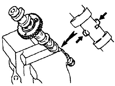
- A) Install the camshaft in a vise as shown.
Note: Do not damage the camshaft as it is fragile.
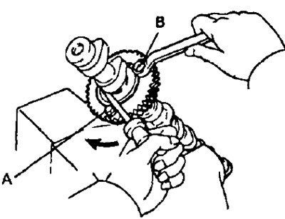
- b) Insert process bolt (A) into the technological hole of the auxiliary gear of the camshaft drive.
- V) Use a screwdriver to turn the auxiliary gear clockwise and remove the service bolt (IN).
Note: Be careful not to damage the camshaft.
- G) Remove the retaining ring with pliers.
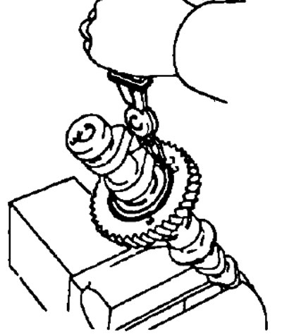
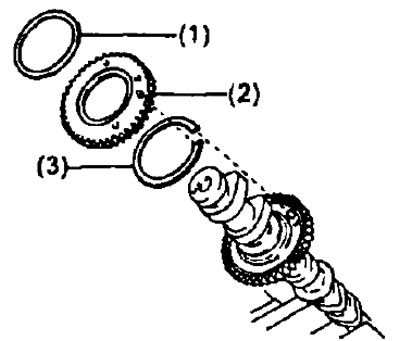
- d) Remove:
- (1) spring washer;
- (2) Auxiliary camshaft drive gear;
- (3) Camshaft gear snap ring.
29. Remove the cylinder head.
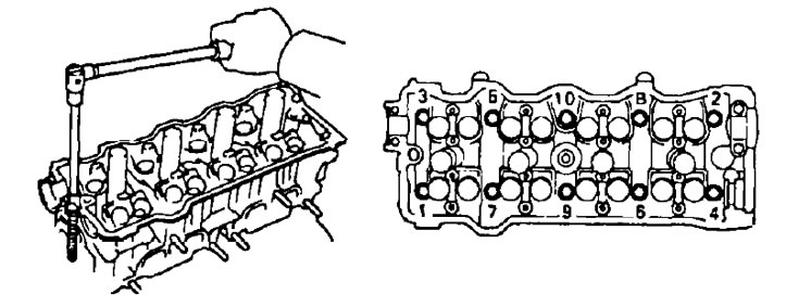
- A) Evenly loosen and remove the 10 cylinder head bolts in several passes in the sequence shown in the figure.
Note: If the bolts are loosened incorrectly, the cylinder head may be deformed or cracked.
- 6) Remove the cylinder head from the guide pins on the cylinder block and lay it on a workbench with wooden blocks and rags.
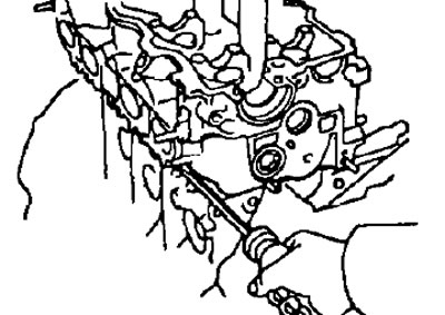
Note: If the block head is difficult to remove, you can use a powerful screwdriver, inserting it into the gas joint, as shown in the figure. However, take care not to damage the surfaces of the head and block, as well as the head gasket.