2. Drain the coolant.
3. Remove the timing belt (see section "timing belt").
4. (5A-FE, 7A-FE) Remove the integrated ignition assembly.
5. (4A-FE) Remove the distributor.
6. Disconnect the accelerator cable with bracket.
7. Disconnect the throttle control cable.
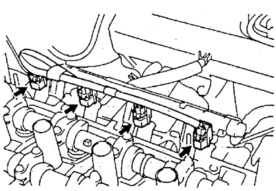
8. Disconnect the injector connectors.
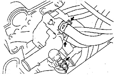
9. Disconnect the power steering air bypass hose.
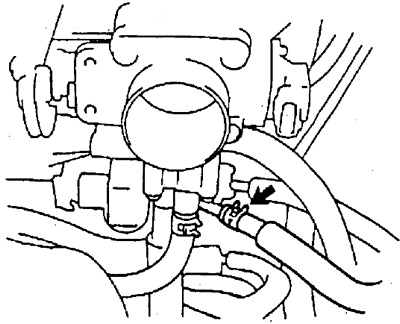
10. Disconnect the vacuum hose of the absolute pressure sensor in the intake manifold.
11. Disconnect the brake booster vacuum hose.
12. Disconnect the vacuum hose from the fuel vapor accumulator.
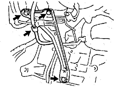
13. (4A-FE, 5A-FE) Disconnect the air hose from the air conditioning solenoid valve.
14. Disconnect the vacuum hose of the vacuum reservoir.
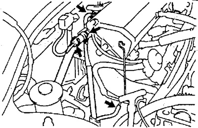
15. Disconnect the connectors and remove the wiring harness.
16. Remove the air filter cover with air duct.
17. Disconnect the radiator inlet and outlet hoses.
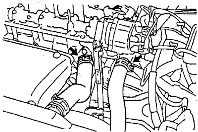
18. Disconnect the heater hose and coolant hose.
19. Remove the intake manifold strut.
20. Disconnect the following hoses:
A) Inlet fuel hose.
b) Fuel return hose.
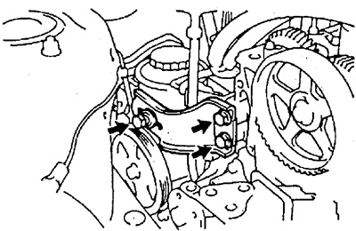
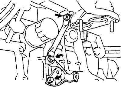
21. Remove the power steering pump by unscrewing the adjusting bolt and remove the adjusting bar.
22. Remove the dipstick and guide by disconnecting the crankshaft position sensor connector (4A-FE).
23. (4A-FE, 5A-FE) Remove the wire harness guard by removing the bolt and two nuts (5A-FE) or by unscrewing the nut and disconnecting the clamp (4A-FE).
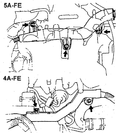
24. (7A-FE) Remove the wire harness guard by first disconnecting the air control electropneumatic valve connector and the coolant temperature gauge sensor connector.
25. (7A-FE) Disconnect the connectors of the evaporative emission system electro-pneumatic valve, idle speed control valve, throttle position sensor, coolant temperature sensor, integrated ignition assembly.
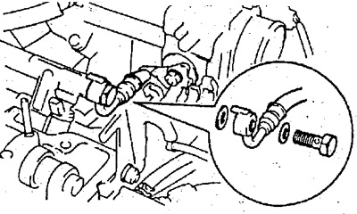
26. Disconnect the #2 coolant inlet.
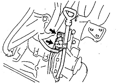
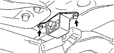
27. Remove the generator.
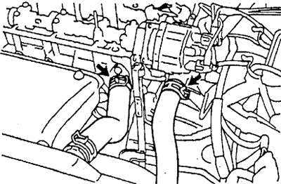
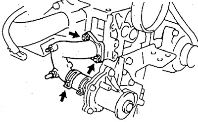
28. (4A-FE, 5A-FE) Disconnect the exhaust pipe bracket.
29. (4A-FE, 5A-FE) Disconnect a reception pipe of system of release.
30. (7A-FE) Disconnect a reception pipe of system of release.
A) Remove 2 bolts and 2 nuts and remove the exhaust pipe bracket.
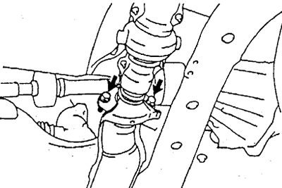
b) Remove the 2 nuts and remove the downpipe lower bracket.
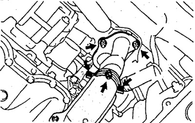
31. Remove the exhaust manifold strut.
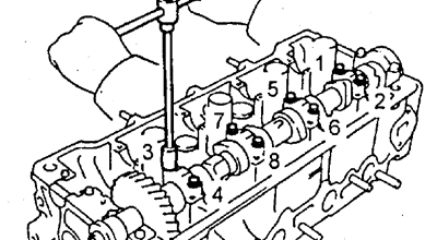
32. Remove the intake and exhaust camshafts. Note: Since the camshaft end play is very small, it is necessary to keep the shaft in a horizontal position to prevent jamming and / or damage to the shaft when dismantling it, for this it is necessary to follow the dismantling procedure below.
A. Remove the intake camshaft.
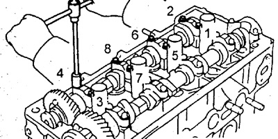
A) Rotate the intake camshaft so that the sub gear locating hole is in the position shown in the figure.
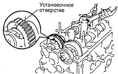
In this case, the cams of the intake camshaft evenly press on the valve lifters of the 1st and 3rd cylinders.
b) Turn away 2 bolts and remove a cover of the 1st bearing of a camshaft.
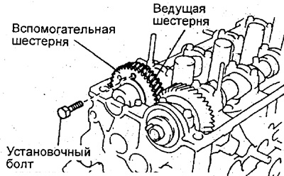
V) Install the intake camshaft sub gear with the drive gear with the set bolt.
- The recommended mounting bolt is M6x1, 16-20 mm long.
Note: When removing the camshaft, make sure that this operation neutralizes the torsional force of the auxiliary gear leaf spring.
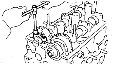
G) Loosen the intake camshaft bearing cap bolts evenly in several passes in the sequence shown in the figure and remove the bolts.
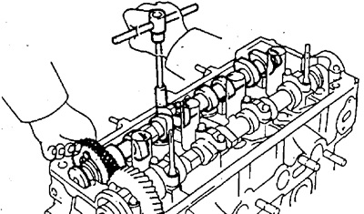
d) Remove the intake camshaft bearing caps and then the camshaft itself.
Note:
- Do not apply excessive force or try to use a screwdriver or any other object as leverage.
- If the camshaft cannot be removed, install the 3rd bearing cap, tighten it, and then loosen the bolts while pulling the shaft by the gear.
B. Remove the exhaust camshaft.
A) Turn the exhaust camshaft with an adjustable wrench until the dowel pin is in. position shown in the figure.
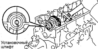
In this case, the cams of the exhaust camshaft evenly press on the valve lifters of the 1st and 3rd cylinders.
b) Turn away 2 bolts and remove a cover of the 1st bearing of a camshaft.
V) Loosen the exhaust camshaft bearing cap bolts evenly in several passes in the sequence shown in the figure and remove the bolts.
G) Remove the exhaust camshaft bearing caps and then the camshaft itself.
Note:
- Do not apply excessive force or try to use a screwdriver or any other object as leverage.
- If the camshaft cannot be removed, install the 3rd bearing cap, tighten it, and then loosen the bolts while pulling the shaft by the gear.
33. Disassemble the intake camshaft.
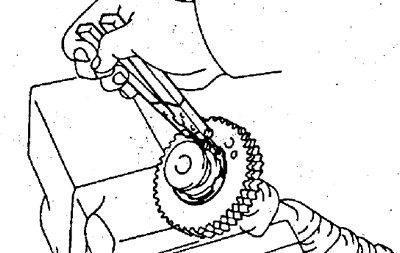
A) Clamp the camshaft with its hexagonal part in a vise.
Note: Be careful not to damage the camshaft.

b) Enter technological bolts (A) And (IN) into the technological holes of the auxiliary gear of the camshaft.
V) Using a screwdriver, turn the camshaft sub gear clockwise and remove the service bolt (WITH).
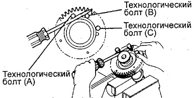
Attention: do not damage the camshaft.
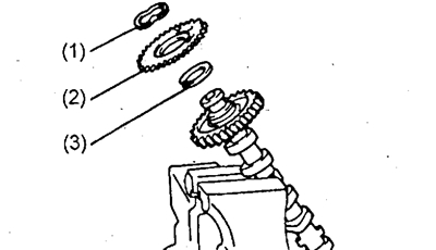
G) Remove the retaining ring with pliers.
d) Remove: spring washer (1), auxiliary camshaft gear (2) and gear spring (3).
34. (4A-FE, 5A-FE) Hang the engine with a hoist.
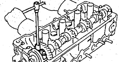
35. Remove the cylinder head.
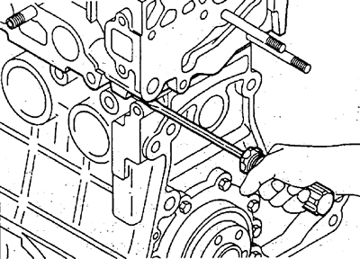
A) Using a suitable tool, loosen and remove the cylinder head bolts evenly over several passes in the sequence shown in the figure, and then remove 10 washers.
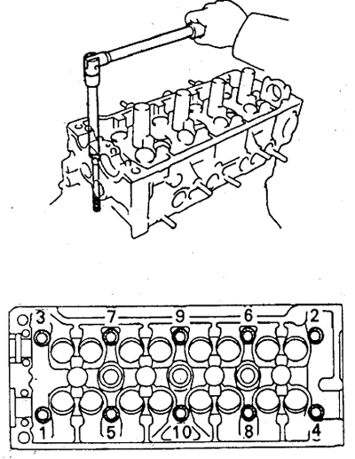
Attention: warping or cracking of the head of the block may be the result of a violation of the sequence of loosening the bolts of the block head.
b) Lift the cylinder head off the dowel pins and place it on a workbench with wood blocks underneath.
Attention: if the block head is difficult to remove, you can use a screwdriver, inserting it into the gas joint, as shown in the figure. However, take care not to damage the surfaces of the head and block, as well as the head gasket.