
Arrangement of joints of piston rings
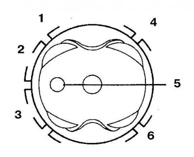
1. Top compression ring; 2. Oil scraper ring expander; 3. Bottom compression ring; 4. The upper disk of the oil scraper ring; 5. Notches (facing the front of the engine); 6. Lower oil scraper disc
Before installing pistons with connecting rods, the surface of the cylinder must be absolutely clean, the edges of the cylinders must be chamfered, and the crankshaft must be installed in the cylinder block.
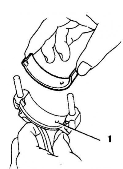
1. Wipe the back of the new upper connecting rod bearing and place it in place on the connecting rod. Make sure the tab on the bushing fits into the groove in the connecting rod and the lubrication holes (1) matched. Do not lubricate the insert. Install the bottom bearing into the connecting rod cap in the same manner.
2. Arrange the joints of the piston rings in accordance with the diagram.
3. Lubricate the pistons and rings with clean engine oil, compress the rings with a tool, leaving a protruding section of the piston.
4. Turn the crankshaft to BDC in the first cylinder, lubricate the cylinder walls with engine oil.
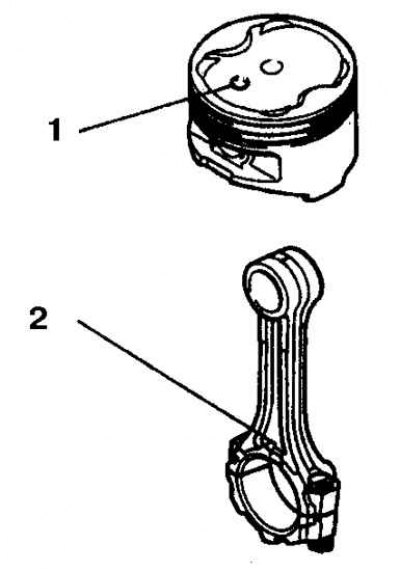
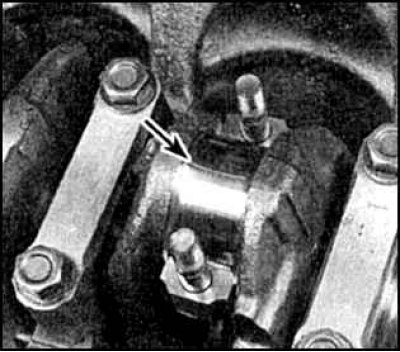
5. Orient the piston so that the notch (1) facing towards the front of the engine (2 - protrusion).
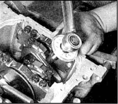
6. Carefully insert the lower part of the piston with the connecting rod into the first cylinder until the tool rests on the cylinder block. Lightly tap the top edge of the mandrel to evenly contact the plane of the cylinder block.
7. Insert the piston into the cylinder by gently tapping the piston head with the wooden handle of the hammer. Don't put in a lot of effort.
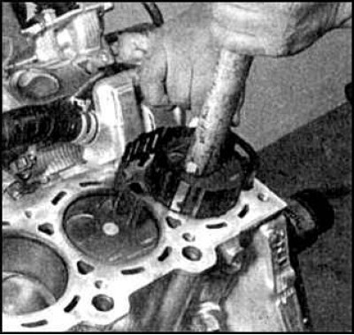
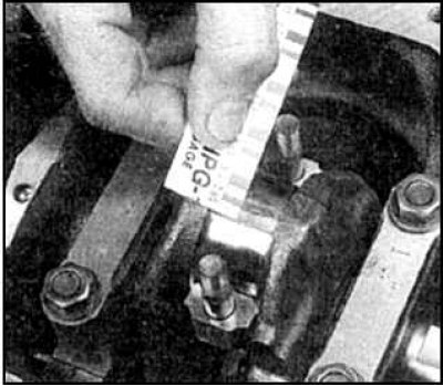
8. Pull the connecting rod to the crankshaft journal and check the clearance in the connecting rod bearing using a piece of gauge (indicated by an arrow). The inspection procedure is no different from the procedure for main bearings (see subsection 3.3.9.3). Rotation of the crankshaft or the slightest ingress of oil on the liners during measurements is not allowed.
9. Tighten the connecting rod cap nuts to the specified torque.
10. Determine the size of the gap. If the clearance is not correct, check that there is no grease or dirt, and again check the neck diameter and correct insert selection.
11. Carefully remove the remnants of the gauge, lubricate the liners and the crankshaft journal, install the cover and evenly tighten the nuts to the specified torque.
12. Repeat these steps for the rest of the connecting rods. Check the freedom of rotation of the assembled crankshaft.
13. After the final installation of pistons with connecting rods, check the freedom of rotation of the crankshaft.
14. Check the end play of the connecting rod (see subsection 3.3.8). Keep in mind that after installing new parts, the play of the connecting rod may be less than normal and grinding of the connecting rods will be required.
15. Assemble and install the engine, guided by the relevant sections