
A) Use a scraper to remove carbon deposits and other carbon deposits from the piston crown.
b) Clean the piston grooves from deposits with a piece of a broken ring.
V) Clean the plunger with solvent and a soft hair brush.
Note: Do not use a metal brush.
2. Check the piston and piston rings.
A. Check clearance between piston and cylinder.
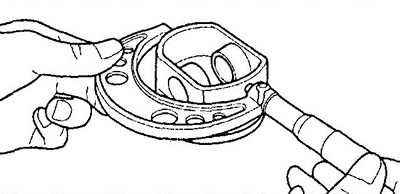
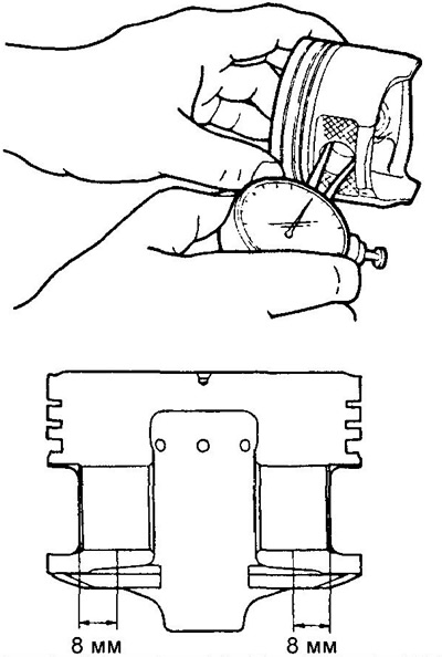
A) Using a micrometer, measure the piston skirt diameter at a distance of 10 mm (KZ series) or 13 mm (EJ-series) from the beginning of the skirt and in a direction perpendicular to the axis of the piston pin, as shown in the figure.
Nominal piston diameter:
- K3-VE - 71.970-71.958 mm
- K3-VE2 - 71.965 - 71.953 mm
EJ series:
- label (1) - 71.965 - 71.975 mm
- label (2) - 71.975 - 71.985 mm
- label (3) - 71.985 - 71.995 mm
b) Measure the diameters of the cylinders in the direction of the engine axis (see above).
V) Determine the clearance between the cylinder and the piston by finding the difference between the measurement of the piston diameter and the cylinder diameter.
Clearance between cylinder and piston:
Nominal:
- EJ series - 0.025 - 0.045 mm
- K3-VE - 0.030 - 0.054 mm
- K3-VE2 - 0.035 - 0.059 mm
Maximum - 0.090 mm
If the clearance is greater than the maximum, bore the cylinder block for oversized pistons. Replace the cylinder block if necessary.
B. Check the gaps between the new compression rings and piston grooves with a flat feeler gauge as shown.
Rated Clearance:
Compression ring #1:
- KZ series - 0.035 - 0.080 mm
- EJ series - 0.040 - 0.060 mm
Compression ring #2:
- KZ series - 0.020 - 0.060 mm
- EJ series - 0.020 - 0.060 mm
Max Clearance:
Compression ring #1:
- KZ series - 0.12 mm
- EJ series - 0.11 mm
Compression ring #2:
- KZ series - 0.11 mm
- EJ series - 0.11 mm
If clearance is greater than allowable, replace rings and/or piston.
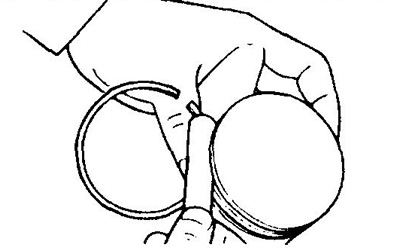
B. Check the clearance in the piston ring lock.
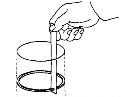
A) Insert the piston ring into the cylinder.
b) Use the piston to push the ring 45 mm from the surface of the cylinder block.
V) Use a flat feeler gauge to measure the gap in the lock.
Nominal clearance in the piston ring lock:
- compression ring No. 1 - 0.20 - 0.30 mm
- compression ring No. 2 - 0.40 - 0.55 mm
- oil scraper ring - 0.15 - 0.50 mm
Max Clearance:
- compression ring No. 1 - 0.65 mm
- compression ring No. 2 - 0.65 mm
oil scraper ring:
- EJ series - 1.00 mm
- KZ series - 0.69 mm
If the gap in the lock is greater than the maximum, replace all piston rings of this cylinder.
3. Check the connecting rod.
A. Using the special tool and a feeler gauge, check the bending of the connecting rod as shown in the illustration.
- The maximum allowable bend per 100 mm length is 0.05 mm
If twisting is more than acceptable, replace the connecting rod along with the connecting rod cap.
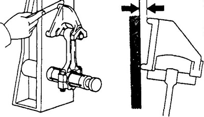
In the same way, check the twisting of the connecting rod, as shown in the figure.
- Maximum twist per 100 mm length - 0.05 mm
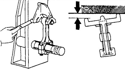
If the twist or bend is greater than the maximum, replace the connecting rod with the connecting rod cap.
B. Check the clearance between the piston pin and the piston bosses.
A) Measure the inner diameter of the piston bosses with a bore gauge.
Piston Boss Inner Diameter:
- KZ series - 18.007- 18.010 mm
b) Using a micrometer, measure the diameter of the piston pin.
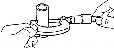
- Piston pin diameter: KZ series - 17.999 - 18.002 mm
G) Subtract the piston pin diameter measurement from the piston boss bore diameter measurement.
Nominal oil clearance between piston pin and piston bosses:
- KZ series - 0.005 -0.011 mm
- EJ series - 0.005 -0.011 mm
If clearance is greater than specification, replace piston or connecting rod.
IN. (KZ series) Measure the outer diameter of the connecting rod bolt with a vernier caliper in the area of greatest wear, as shown in the figure.
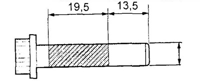
- Nominal diameter - 7.7 mm
If the diameter is less than acceptable, replace the bolt.