
Causes of destruction of crankshaft bearings are insufficient lubrication due to improper assembly, contamination and penetration of foreign particles, frequent engine overloads, corrosion, etc. Regardless of the cause that caused the destruction of the bearings, it should be eliminated.
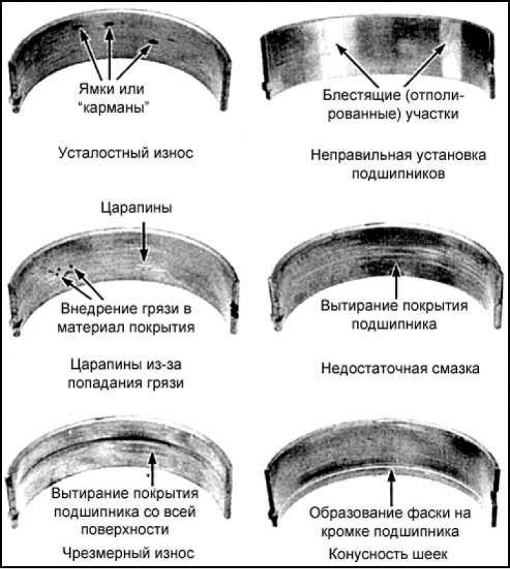
Types of wear of main and connecting rod bearings
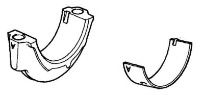
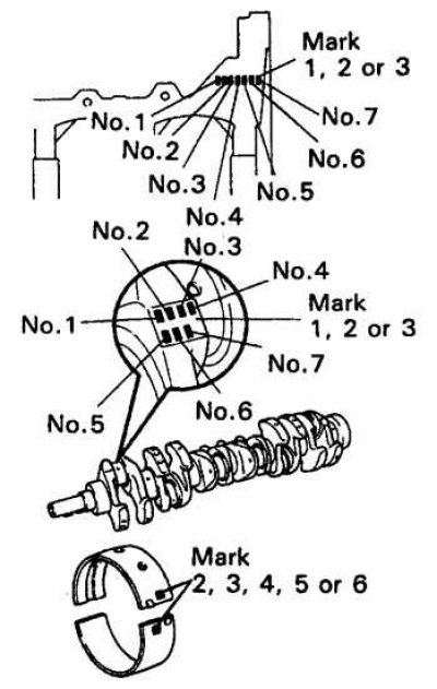
Selection of main bearings
Diagram for selecting connecting rod bearings on 3F-E engines
| Marking A | 1.484 - 1.488 mm |
| Marking B | 1.488 - 1.492 mm |
| Marking C | 1.492 - 1.496 mm |
Diagram for selection of crankshaft connecting rod bearings on 3F-E engines
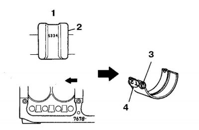
1. Crankshaft; 2. Central counterweight; 3. Bearing N3; 4. Size group of the bearing
Bearing marking | |||||||||
| Number on the crankshaft | 3 | 4 | 5 | ||||||
| Number on the cylinder block | 6 | 7 | 8 | 6 | 7 | 8 | 6 | 7 | 8 |
| Bearing size group* | T3 | T4 | T5 | T2 | T3 | T4 | T1 | T2 | T3 |
* Example: Crankshaft number 5, cylinder block number 7 = size group T2.
Main bearing diameter and main bearing bore diameter on 3F-E engines
| Crankshaft journal diameter | № | mm |
| Marking-3 | N1 | 66.972 – 66.980 |
N2 | 68.472 – 68.480 | |
N3 | 69.972 – 69.980 | |
N4 | 71.472 – 71.480 | |
Marking-4 | N1 | 66.980 – 66.988 |
N2 | 68.480 – 68.488 | |
N3 | 69.980 – 69.988 | |
N4 | 71.480 – 71.488 | |
Marking-5 | N1 | 66.988 – 66.996 |
N2 | 68.488 – 68.496 | |
N3 | 69.988 – 69.996 | |
N4 | 71.488 – 71.496 | |
| Main bearing bore diameter | N | mm |
Marking-6 | N1 | 72.010 – 72.018 |
N2 | 73.510 – 73.518 | |
N3 | 75.010 – 72.018 | |
N4 | 76.510 – 76.518 | |
Marking-7 | N1 | 72.018 – 72.026 |
N2 | 73.518 – 73.546 | |
N3 | 75.018 – 75.026 | |
N4 | 76.518 – 76.526 | |
Marking-8 | N1 | 72.026 – 72.034 |
N2 | 73.526 – 73.534 | |
N3 | 75.026 – 75.034 | |
N4 | 76.526 – 76.524 |
Diagram for selection of standard connecting rod bearings on 1FZ-FE engines
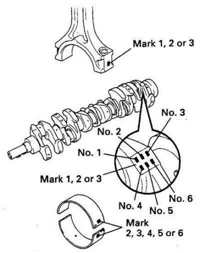
Inflicted number | |||||||||
| Marking on the connecting rod | 1 | 2 | 3 | ||||||
| Number on the crankshaft | 1 | 2 | 3 | 1 | 2 | 3 | 1 | 2 | 3 |
| Bearing size marking* | 2 | 3 | 4 | 3 | 4 | 5 | 4 | 5 | 6 |
* Example: Connecting rod number 3 + crankshaft number 1 = Bearing size group 4.
Diagram for selection of standard crankshaft main bearings on 1FZ-FE engines
| Inflicted number | |||||||||
| Marking on the cylinder block | 1 | 2 | 3 | ||||||
| Number on the crankshaft | 1 | 2 | 3 | 1 | 2 | 3 | 1 | 2 | 3 |
| Bearing size marking* | 2 | 3 | 4 | 3 | 4 | 5 | 4 | 5 | 6 |
* Example: Number on cylinder block 2 + number on crankshaft 1 = Bearing size group 3.
Main bearing diameter and main bearing bore diameter on 1FZ-FE engines
| Main bearing bore diameter: | |
- marking 1 | 74.026 – 74.032 mm |
| – marking 2 | 74.032 – 74.038 mm |
| – marking 3 | 74.03 – 74.044 mm |
| Crankshaft journal diameter: | |
- marking 1 | 68.994 – 69.000 mm |
| – marking 2 | 68.988 – 68.994 mm |
| – marking 3 | 68.982 – 68.988 mm |
| Thickness of standard bearings: | |
– marking 2 | 2.489 – 2.492 mm |
| – marking 3 | 2.49 – 2.495 mm |
| – marking 4 | 2.495 – 2.498 mm |
| – marking 5 | 2.498 – 2.501 mm |
| – marking 6 | 2.501 – 2.504 mm |
1. If bearings of standard size groups are installed, then the new bearing is selected according to the numbers printed on the replaced one, as well as according to the numbers on the cylinder block and crankshaft using tables.
2. If the crankshaft was ground, then the bearings should be selected at the car service in which the grinding was performed.
3. After selecting the bearings, measure the clearance in the journals (see subsection 3.3.8.2).
4. In the factory, when assembling the engine, bearings with different color markings are installed, which are applied to the edge of the bearing shell.
5. Bearing size markings are usually on the side of the bearing facing the rear of the crankshaft, with the exception of the rear main bearing, which is marked on the side facing the front of the crankshaft.
6. It is allowed to install upper and lower liners from different size groups. For example, to correct a gap of 0.0125 mm, a standard liner is sometimes used with a 0.025 mm reduced diameter liner.
Attention! It is forbidden to install a pair of liners if the difference in their diameters exceeds 0.025 mm. Inserts that differ in size should be installed either all on top or all on the bottom.