
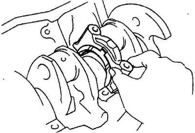
2. Remove the bolts and remove the main bearing caps or cap assembly and arrange the bearing caps in the correct order for reinstallation. Wipe the main bearing mounting points with a clean, wax-free cloth.
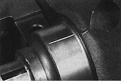
Checking the operating clearance of the bearing
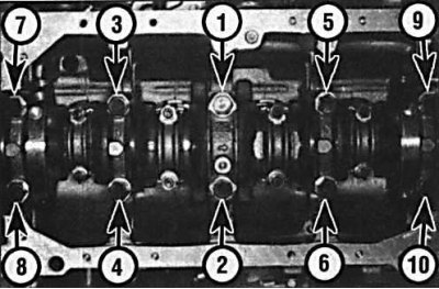
The sequence of tightening the bolts of the main bearing caps on the four-cylinder engine
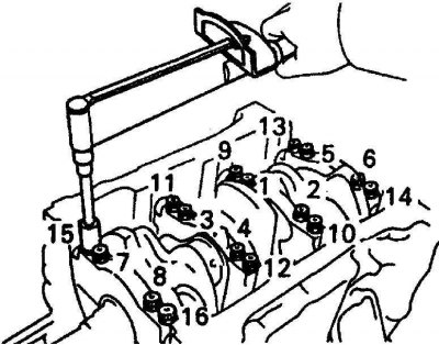
The sequence of tightening the bolts of the main bearing caps on the 3VZ-FE engine
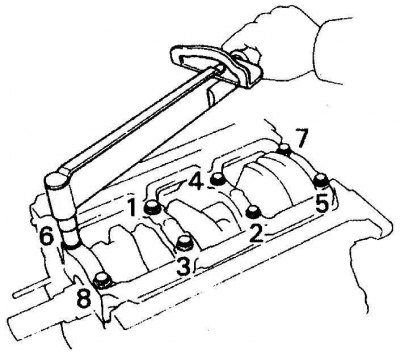
The sequence of tightening the bolts of the main bearing caps on the 1MZ-FE engine
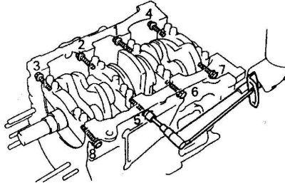
The sequence of tightening the side bolts of the main bearing caps on the 1MZ-FE engine
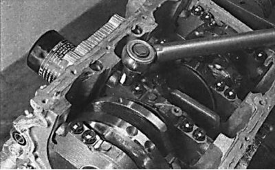
Tightening the bolts of the main bearing caps on the V6 engine
1. Clean the back of the bearings and their location in the cylinder block and main bearing caps.
2. Install the liners in their places in the engine block.
3. One method that involves having a micrometer to measure hole diameters (see item 4), is to install the main bearing caps together with the liners on the cylinder block and screw them to the required torque. Measure the inside diameter of each assembled pair of bearing shells. Measure the diameter of each crankshaft main journal. Subtract the corresponding diameter of the crankshaft main journal from the measured bearing diameter.
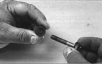
4. Second (and more accurate) the method is to use a product known as Plastigage. This is a round plastic rod that is compressed between the bushing and the crankshaft journal. After removing the main bearing cap, the deformed plastic rod is measured with a special gauge, which is included in the Plastigage kit. The procedure for using Plastigage is as follows.
4a. On the liners installed in the cylinder block, install the crankshaft without lubrication. The crankshaft journals and liners must be perfectly clean and dry.
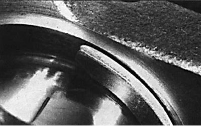
4b. Cut off a few pieces of the plastic Plastigage rod (they should be slightly shorter than the width of the main bearings) and install on each crankshaft journal.
4c. Install the covers with the bottom liners and tighten the mounting bolts to the required torque. Do not rotate the crankshaft while measuring the clearance using the Plastigage method (see fig. Tightening sequence of the main bearing cap bolts on a four-cylinder engine, Tightening sequence of the main bearing cap bolts on the 3VZ-FE engine, Tightening sequence of the main bearing cap bolts on the 1MZ-FE engine, Tightening sequence of the side bolts of the main bearing caps on the 1MZ-FE engine).
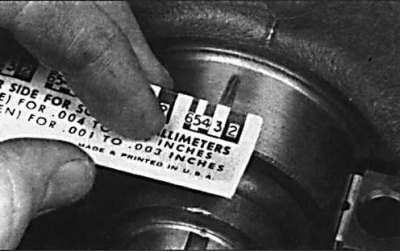
4y. Unscrew the cover of the insert attachment, remove it and attach a scale ruler to the deformed plastic rod. By comparing the width of the deformed plastic rod with the reference width on the scale bar, determine the amount of gap.
4d. Finally, thoroughly clean any traces of Plastigage from the liners and crankshaft.
Final installation of the crankshaft
1. Remove the crankshaft from the cylinder block.
2. Clean the back of the bushing and its mounting location in the cylinder block and main bearing caps. Put those earbuds back in place.
3. Lubricate the bearing surface with clean engine oil and install the crankshaft into the engine block.
 |  |
4. Install thrust washers. On four-cylinder engines, thrust half rings are installed near the No. 3 main bearing, and on V6 engines, near the No. 2 main bearing. Measure the end play of the crankshaft.
5. Lubricate the lower bearing shells in the main bearing caps with clean engine oil and install the main bearing caps to the cylinder block.
6. Lubricate the threads of the main bearing cap bolts with a thin layer of engine oil and screw in the bolts, tightening them to the required torque. On the 1MZ-FE V6 engine, first tighten the lower mounting bolts to the required torque, and then the side mounting bolts. When installing bolts, new washers must be used.
7. Check that the crankshaft rotates smoothly and without binding.
8. Install a new crankshaft rear O-ring, then install the crankshaft rear cover onto the cylinder block.