
2. Adopt the support bracket and tighten the 3 bolts. Tightening torque 19 Nm.
3. Install the main shaft.
- A) Using a special tool, install the retaining ring
- b) Install the main shaft assembly with bearing, thrust washer and spring.
- V) While holding the shaft, install the circlip.
4. Install the wire harness clip.
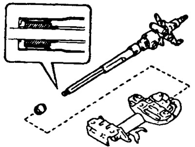
5. Pick up bolts according to a label on the top tube of a steering column.
Select the bolt for one side first and then for the other side, as the left and right bolts have different shapes.
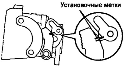
Attention: select the bolt corresponding to the mark on each side of the steering column tube.
6. Install the top tube of the steering column with the main shaft.
- A) Install the main shaft coupling.
Note: Orient the coupler as shown.
- b) Install the upper steering column tube with the main shaft into the lower steering column tube.
- V) Using a hammer, install the 2 steering column bolts.
Attention: do not mix up the left and right bolts.
7. Install the pivot pin, 2 washers, tilt lever, and secondary tilt lever.
- A) Establish an axis of levers.
- b) Install the 2 washers and the tilt adjustment lever and the auxiliary tilt adjustment lever.
8. Install two pawl retainers.
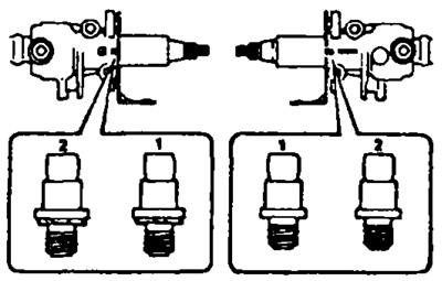
9. Select the pawl bushings so that there is no gap.
| Adjustment lever side | Secondary arm side | Outer diameter, mm |
| 0 | A | 11,483-11,493 |
| 2 | 6 | 11,499-11,509 |
| 3 | 7 | 11,494-11,504 |
| 4 | 8 | 11,488-11,498 |
10. Install pawls.
- A) Insert bushings into pawls.
- b) Temporarily install pawls, bolt, washer and nut.
11. Adjustment of dogs.
- A) Engage the pawl located on the side of the angle adjustment lever to the center of the ratchet.
- b) By turning the bushing on the side of the sub-lever angle adjustment, engage the pawl located on the side of the sub-tilt adjustment lever fully into the ratchet.
- V) Tighten the nut. Tightening torque 7.8 Nm.
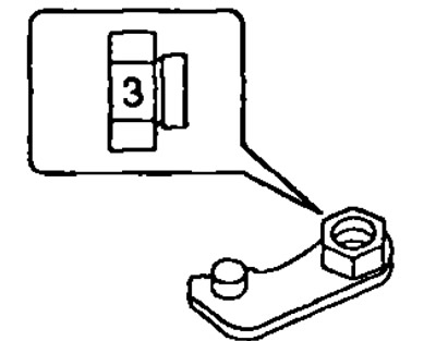
12. Pick up dog latches.
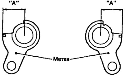
- A) With hooked pawls and ratchets, install pawl locks.
- b) Align the alignment marks on the latch and pawl by slightly turning the pawl latch.
- V) If the alignment marks do not match: select the pawl lock using the table.
| Adjustment lever side | Sub adjustment lever side | Size "A" mm |
| 11 | A | 12,65-12,75 |
| 12 | IN | 12,55-12,65 |
| 13 | WITH | 12,45-12,55 |
| 14 | D | 12,35-12,45 |
| 15 | E | 12,25-12,35 |
- G) After selecting the pawls, check that the pawl and ratchet are fully engaged on both sides.
13. Install 2 tilt arm holders, 2 washers and tighten nuts. Tightening torques:
- from the axis of the levers 7.8 Nm.
- on the side of the steering column bolts 12 Nm.
14. Install compression springs.
- A) Install bushings for each spring.
- b) Install 2 bushings on the spring.
- V) Tighten the bolts. Tightening torque 7.8 Nm.
15. Install two extension springs.
16. Install the ignition lock bracket. Tighten 2 new cone head bolts until the bolt heads shear off.
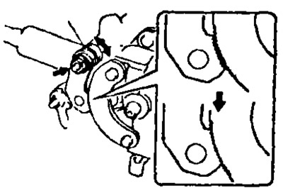
17. Checking the operation of the steering column tilt adjustment mechanism.
- A) Check that there is no axial play at the end of the main shaft
- b) With the mainshaft in the neutral position, pull the tilt adjustment lever and check that the mainshaft is raised to its highest position.
- V) Lower the main shaft and check that it locks in the lowest position.