
Note. When fixing in a vise, do not allow strong squeezing of parts.
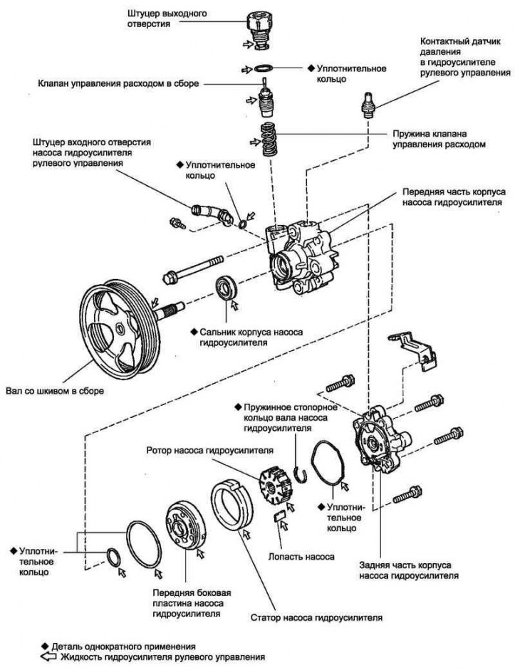
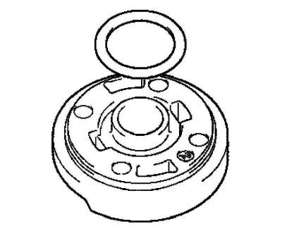
Pic. 5.31. Power Steering Pump Components
When assembling, lubricate the parts marked with arrows in Figure 5.31 with power steering fluid.
Remove the front right wheel.
Remove the #1 motor bottom guard.
Remove the right lower engine guard.
Remove the fan and alternator V-belt.
Disconnecting hose No. 1 connecting the hydraulic booster reservoir and pump
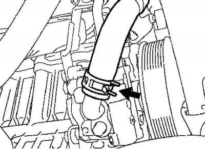
Pic. 5.32. Hose clamp #1
Remove the clamp and remove the hose No. 1 connecting the hydraulic booster reservoir and pump (pic. 5.32).
Disconnecting the power steering pump feed pipe
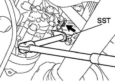
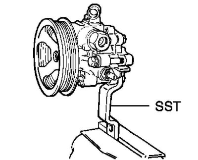
Pic. 5.33. Disconnecting the power steering pump feed pipe
Disconnect the power steering pump assembly using the SST tool (pic. 5.33).
Turn out a bolt and disconnect a collar of the submitting tube.
Removing the power steering pump assembly
Disconnect the connector from the oil pressure switch.
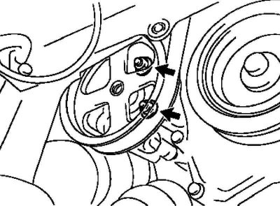
Pic. 5.34. Power steering pump mount
Remove the two bolts and two nuts, then remove the power steering pump assembly (pic. 5.34).
Fixing in a vice of the pump of the hydraulic booster assy
Pic. 5.35. Installing the power steering pump in a vise
Clamp the power steering pump assembly in a vise using the SST tool (pic. 5.35).
Removal of the union of an entrance opening of the pump of the hydraulic booster of a steering
Turn out a bolt and the union of an entrance opening of the pump of the hydraulic booster of a steering.
Remove the O-ring from the power steering pump inlet fitting.
Removing the power steering pump rear bracket
Loosen the bolt and remove the power steering pump rear bracket.
Removing the flow control valve
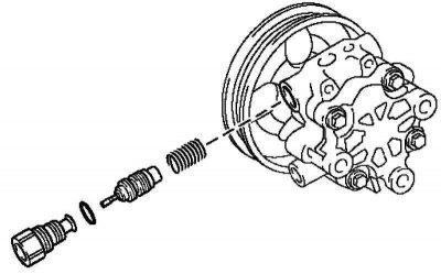
Pic. 5.36. Pump outlet fitting
Unscrew the pump outlet (pic. 5.36).
Remove the O-ring from the pump outlet fitting.
Remove the flow control valve and spring.
Remove the power steering pressure sensor.
Note. A dropped or damaged sensor must be replaced with a new one.
Removing the rear of the power steering pump housing
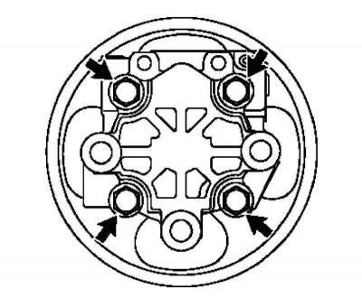
Pic. 5.37. Fastening of the rear part of the hydraulic booster pump housing
Remove the four bolts and disconnect the rear of the power steering pump housing from the front of the housing (pic. 5.37).
Remove the O-ring from the back of the power steering pump housing.
Extraction of a shaft with a pulley
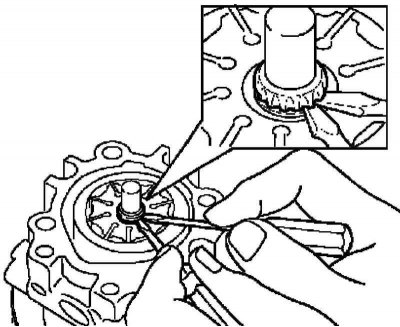
Pic. 5.38. Removing the circlip
Using two screwdrivers, remove the circlip from the pulley shaft (pic. 5.38).
Remove the pulley shaft.
Removing the power steering pump rotor
Remove 10 pump vanes.
Remove the power steering pump rotor.
Remove the power steering pump stator.
Removing the power steering pump front side plate
Remove the front side plate from the front of the power steering pump housing.
Pic. 5.39. Sealing ring
Remove the o-ring from the front side plate (pic. 5.39).
Pic. 5.40. Sealing ring of a forward part of the case of the pump of the hydraulic booster
Remove the O-ring from the front of the power steering pump housing (pic. 5.40).
Extraction of an epiploon from the case of the pump of the hydraulic booster
Pic. 5.41. Oil seal removal
Remove the seal with a screwdriver (pic. 5.41).
Note. Be careful not to damage the front of the power steering pump housing.
Checking the power steering pump shaft and bushing in the front of the housing
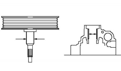
Pic. 5.42. Checking the power steering pump shaft
Using a micrometer and a dial indicator for the holes, measure the clearance between the shaft and the pump casing (pic. 5.42).
Maximum allowable clearance: 0.07 mm.
If the clearance exceeds the maximum allowable value, replace the power steering pump assembly.
Checking the rotor and vanes of the power steering pump
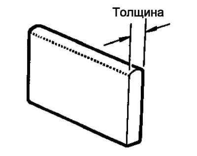
Pic. 5.43. Pump blade thickness
Measure the thickness of the pump blades with a micrometer (pic. 5.43).
Nominal thickness: 1.405–1.411 mm.
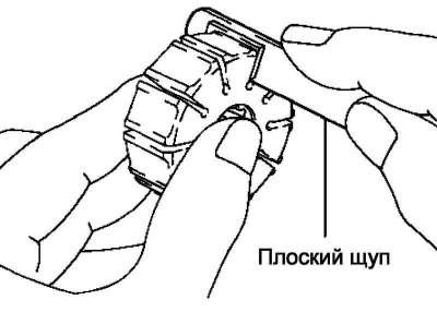
Pic. 5.44. Measuring the gap between the blades and the walls of the grooves of the pump rotor
Use a flat feeler gauge to measure the gap between the vanes and the groove walls of the pump rotor (pic. 5.44).
Maximum allowable clearance: 0.03 mm.
If the clearance exceeds the maximum allowable value, replace the power steering pump assembly.
Checking the flow control valve
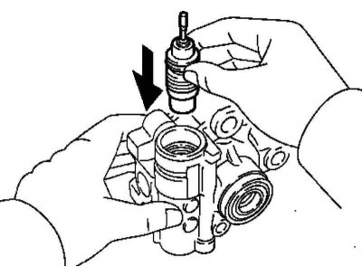
Pic. 5.45. Checking the free movement of the valve
Lubricate the flow control valve with power steering fluid and check that the valve slides smoothly into the port under its own weight (pic. 5.45).
If the valve does not fit well, replace the power steering pump assembly.
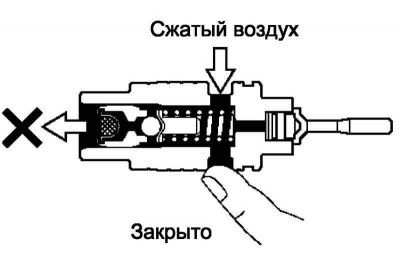
Pic. 5.46. Valve leak test
Make sure the flow control valve is tight. Close one of the holes and supply air at a pressure of 392–490 kPa into the opposite hole. Make sure air is not escaping from the holes at the ends of the valve (pic. 5.46).
If the valve leaks, replace the power steering pump assembly.
Checking the valve spring
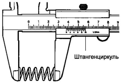
Pic. 5.47. Valve Spring Length Measurement
Use a caliper to measure the free length of the valve spring (pic. 5.47).
Minimum allowable length: 36.9 mm.
If the free length of the valve spring is less than the allowable length, replace the power steering pump assembly.
Checking the Outlet Fitting
If the outlet to the fitting in the pump housing is damaged, which may cause fluid leakage, replace the power steering pump assembly.
Installing the stuffing box in the hydraulic booster pump housing
Lubricate the sealing lip of the new oil seal with power steering fluid.
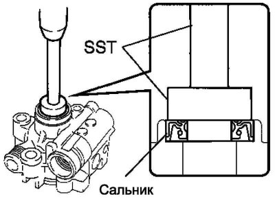
Pic. 5.48. Scheme of pressing the stuffing box
Using an SST tool and a hammer, drive in the new oil seal (pic. 5.48).
Note. Care must be taken to ensure that the oil seal is correctly oriented in the power steering pump housing.
Installing a shaft with a pulley
Lubricate the bushing surface of the front housing with power steering fluid.
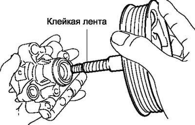
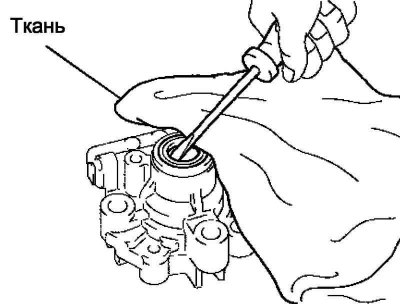
Pic. 5.49. Installing a shaft with a pulley
Carefully insert the shaft with the pulley (pic. 5.49).
Note. Be careful not to damage the lip of the pump seal.
Note. After installing the shaft with the pulley, check that the seal lip is correctly oriented.
Installing the Power Steering Pump Front Side Plate
Lubricate a new O-ring with power steering fluid and install it on the front of the pump housing.
Lubricate a new O-ring with power steering fluid and install it on the pump front side plate.
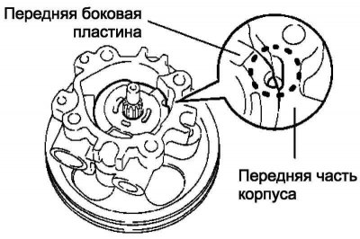
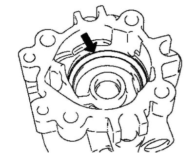
Pic. 5.50. Installation diagram of the front side plate of the power steering pump
Install the front side plate, aligning the notch on it with the notch on the front of the pump housing (pic. 5.50).
Note. Care must be taken to ensure that the front side plate of the pump is correctly oriented.
Installing the power steering pump stator
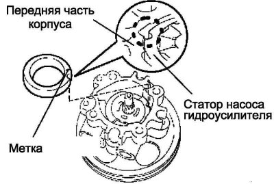
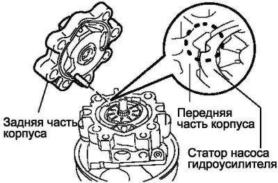
Pic. 5.51. Stator installation diagram
Align the notch of the stator with the notch of the front side plate and install the stator with the mark facing out (pic. 5.51).
Note. Ensure that the stator is correctly installed in the power steering pump housing.
Installing the power steering pump rotor
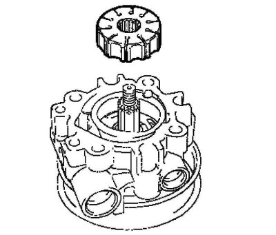
Pic. 5.52. Rotor installation
Install the power steering pump rotor (pic. 5.52).
Note. The direction of the power steering pump rotor does not matter.
Lubricate 10 pump vanes with power steering fluid.
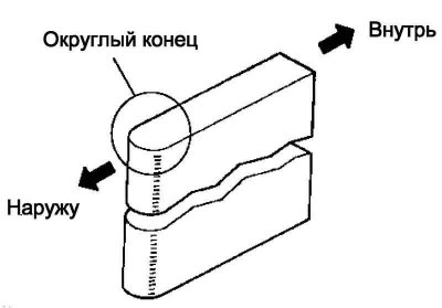
Pic. 5.53. Pump blade installation diagram
Install the blades with the rounded end facing out (pic. 5.53).
Installation of a snap ring of a shaft of the pump of the hydraulic booster
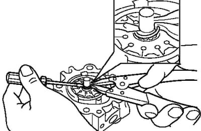
Pic. 5.54. Installing the spring ring
Using a puller and a screwdriver, install the circlip onto the pulley shaft (pic. 5.54).
Installing the rear of the power steering pump housing
Lubricate a new O-ring with power steering fluid and install it on the back of the pump housing.
Pic. 5.55. Installing the rear of the power steering pump housing
Align the drive pin on the rear of the pump housing with the notches on the stator, on the front side plate and on the front of the pump housing, and secure the rear of the housing with four bolts (pic. 5.55).
Tightening torque: 22 Nm.
Checking the preload
Make sure the pump rotates without binding or abnormal noise.
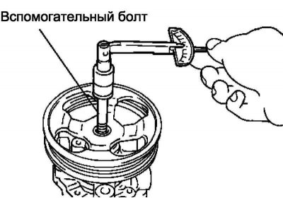
Pic. 5.56. Secondary Bolt Installation
Screw in without tightening the auxiliary bolt (pic. 5.56).
Recommended auxiliary bolt sizes:
- Thread diameter: 10 mm.
- Thread pitch: 1.25 mm.
- Bolt length: 50 mm.
Using a torque wrench, check the moment of resistance to the rotation of the pulley.
The moment of resistance to rotation: no more than 0.27 Nm.
If the moment of resistance to rotation does not correspond to the specified value, check the oil seal.
Installing the contact sensor
oil pressure in the power steering
Lubricate a new O-ring with power steering fluid and install it to the power steering pressure sensor.
Install the oil pressure sensor to the power steering pump assembly.
Tightening torque: 21 Nm.
Flow Control Valve Installation
Lubricate the valve spring and flow control valve with power steering fluid.
Insert valve spring and flow control valve.
Lubricate a new O-ring with power steering fluid and install it on the pump outlet fitting.
Screw the fitting into the pump outlet.
Tightening torque: 69 Nm.
Installation of the union of an entrance opening of the pump of the hydraulic booster of a steering
Lubricate a new O-ring with power steering fluid and install it on the power steering pump inlet fitting.
Establish the union of an entrance opening of the pump of the hydraulic booster and fix it with a bolt.
Tightening torque: 12 Nm.
Installing the Power Steering Pump Rear Bracket
Install the power steering pump rear bracket and secure with the bolt.
Tightening torque: 44 Nm.
Installing the power steering pump assembly
Install the power steering pump assembly and secure with two bolts and nuts.
Tightening torque: 37 Nm.
Connect the connector to the power steering oil pressure sensor.
Note. Avoid getting oil on the connector.
Connecting the power steering pump
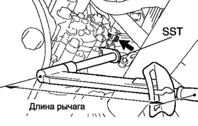
Pic. 5.57. Connecting the power steering pump
Connect Feed Tube Assembly with SST Tool (pic. 5.57).
Tightening torque: 41 Nm.
Note. Use a torque wrench with a leverage of 345 mm.
Note. The tightening torque is specified for the SST position parallel to the torque wrench.
Install the feed tube clamp and secure it with the bolt.
Tightening torque: 7.8 Nm.
Connecting hose No. 1 connecting the hydraulic booster reservoir and pump
Connect and secure with a clamp hose No. 1 connecting the hydraulic booster reservoir and pump.
Install the fan and alternator V-belt.
Fill fluid into the power steering.
Bleed the air from the power steering.
Check the tightness of the system.
Install the right lower engine guard.
Install the #1 engine bottom guard.
Install the right front wheel.
Tightening torque: 103 Nm.