
Removing
Note. The TR sensor is located on the front side of the transmission.
1. Disconnect the ground wire from the battery (see paragraph 1 of chapter 5).
2. Raise the vehicle and place secure supports under it.
3. Disconnect the TR sensor electrical connector (pic. 12.3).
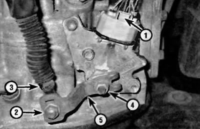
Pic. 12.3. First, disconnect the electrical connector and remove the control shaft lever from the TR sensor: (1) press the locking tab and disconnect the electrical connector of the TR sensor; (2) unscrew the nut; (3) disconnect the shift cable from the control shaft lever; (4) unscrew the nut; (5) and remove the control shaft lever from the manual valve shaft
4. Remove the nut that secures the shift cable to the control shaft lever and disconnect the cable from the lever.
5. Remove the nut that secures the control shaft lever to the manual valve shaft, remove the appropriate washer, and remove the control shaft lever from the manual valve shaft.
6. Fold back the lock tabs (pic. 12.6) and loosen the nut on the manual valve shaft.
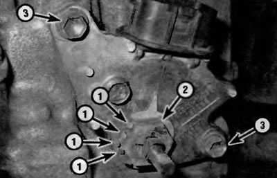
Pic. 12.6. To disconnect the TR sensor from the transmission: (1) Bend back the tabs of the lock washer; (2) Loosen the nut on the manual valve shaft; (3) Turn out bolts of fastening of the sensor TR and remove the sensor
7. Turn out bolts of fastening of the gauge and remove the gauge.
Installation
8. To install the sensor, slide it onto the manual valve shaft and then install the bolts, but do not tighten them.
9. Install a new lock washer and thread the nut onto the manual valve shaft.
10. Place the control shaft lever on the manual valve shaft, turn it counterclockwise through all ranges (when moving to the next range, it will emit a click), until it stops, then rotate it clockwise two clicks. Now it is in the neutral position.
11. Align pointer on lock washer with neutral reference line (pic. 12.11).
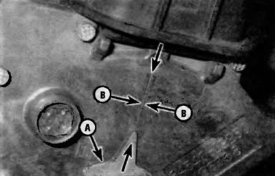
Pic. 12.11. To adjust the position of the TR sensor, align the pointer on the lock washer (A) with baseline neutral overlay (IN) on the gearbox housing
12. Install a new lock washer, thread the nut onto the manual valve shaft, tighten it securely, and then bend the tabs of the lock washer at the edge of the nut.
13. The rest of the installation is performed in the reverse order of removal.