
Design Description
Application. ACIS is only used on V6 models. It is not available on four-cylinder engines.
1. When the intake valve is closed, the incoming air flowing through the intake port hits the closed valve, is compressed by its own inertia and «rebounds» back into the inlet and collection chamber, then «rebounds» into the intake port, where it strikes a closed intake valve, etc. Under certain combinations of load and engine speed, this uncontrolled compression wave is in phase with the opening of the intake valve, causing an increase in air intake and improved torque. But in most load/speed combinations this doesn't happen because the length of the intake manifold is fixed. Air intake system with adjustable geometry (ACIS) takes advantage of this phenomenon by changing the effective length of the intake manifold to control the pulsation of this compression wave. The result is improved torque and power throughout the V6 engine's operating range, especially high-load torque at lower engine speeds. By improving torque and power at low engine speeds, ACIS improves overall vehicle handling and fuel efficiency.
Models 1999-2003
2. On models 1999-2003 The ACIS system includes a throttle body with two cylinders and a pair of air intake control valves. One air intake control valve is installed inside the throttle body and the other is inside the air intake accumulator chamber. A vacuum actuated actuator activates each air intake control valve, and a PCM controlled vacuum switching valve (VSV) actuates each actuator. This setting allows for three different intake manifold lengths.
3. Under heavy engine loads in the low rpm range, the intake pulses are very long. The PCM includes both VSVs, which allow vacuum in the intake system to actuate two actuators that close both air intake control valves. When both valves are closed, the intake air line, throttle body and entire intake manifold (collection chamber and inlets) work like one big long intake manifold to take advantage of those long intake pulses.
4. Under heavy engine loads in the midrange RPM range, the intake pulses are relatively long. The PCM turns on the VSV that controls the air intake control valve in the intake manifold and turns off the VSV that controls the air intake control valve in the throttle body. The intake manifold and the air intake plenum now work as an intake manifold.
5. In idling, light loads and low-speed operation without load, the intake pulses are short. The PCM turns off both VSVs, which allow both intake air control valves to open, reducing the effective length of the intake manifold to just the length of the intake ports themselves.
2004 and later models
6. On 2004 and later models with a V6 engine, ACIS is simplified. There is only one air intake control valve, which is located in the air intake storage chamber. Like the earlier units, it is activated by a vacuum actuated actuator which in turn is actuated by a PCM controlled VSV. Not these models, there are only two options for the effective length of the intake manifold.
7. Under heavy engine loads at low engine speeds, the PCM engages the VSV, which closes the intake air control valve, providing an effective intake manifold length that includes the intake air line, throttle body, and entire intake manifold (including storage chamber and inlets).
8. At idle, light loads, and high RPM no-load intake pulses are short, the PCM turns off the VSV, which opens the air intake control valve, reducing the effective length of the intake manifold to just the length of the direct intake ports.
9. On these models, there is no change in the effective length of the intake manifold for heavy engine loads in the medium speed range. Not all of these models are equipped with an intelligent electronic throttle control system (ETCS-i), which provides slightly more precise control of the throttle valve, enclosed in a corresponding housing, than conventional intake systems that use an accelerator cable.
10. Lexus models are also equipped with a special air intake control system that changes the effective volume of the air filter housing (see next paragraph).
Replacing elements
Vacuum switching valves (VSV)
Note. This procedure applies to all VSVZ valves. The accompanying drawings in this paragraph show the valves used on 1999-2003 models. 2004 and later models use one VSV, but it is located on a similar support bracket in the same location as the two VSVs shown here.
11. Remove the engine cover (see paragraph «Intake manifold - removal and installation» in chapter 2B).
12. Vacuum switching valves are located on a support bracket located on the front side of the intake manifold (pic. 15.12).
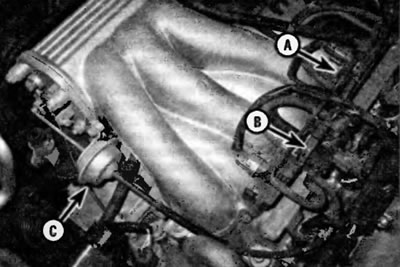
Pic. 15.12. On models 1999-2003. with VG engine vacuum switching valves (VSV) for air intake system with adjustable geometry (ACISI are located on this support bracket on the front side of the intake manifold
A - VSV valve for the actuator on the throttle body
B - VSV valve for the actuator on the intake manifold
C - Intake manifold actuator (the throttle body actuator, which is on the underside of the throttle body, is not visible in this photo)
13. Disconnect the VSV electrical connector (pic. 15.13).
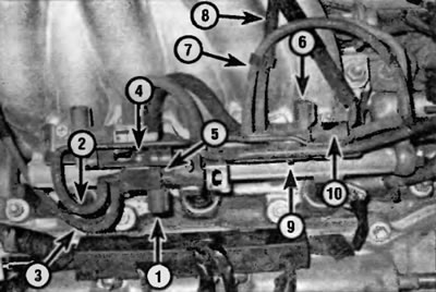
Pic. 15.13. Details of removing and installing the vacuum switching valve (VSV):
1 - Disconnect the VSV electrical connector for the intake manifold actuator
2 - Disconnect the vacuum supply hose (from intake manifold)
3 - Disconnect the vacuum signal hose (to the intake manifold actuator)
4 — Turn out the screw of fastening of the valve VSV
5 - Remove the VSV from the support bracket
6 - Disconnect the VSV electrical connector for the throttle body actuator
7 - Disconnect the vacuum supply hose (from intake manifold)
8 - Disconnect the vacuum signal hose (to throttle body actuator)
9 — Turn out the screw of fastening VSV
10 - Remove the VSV from the support bracket
14. Clearly label the vacuum hoses, then disconnect them from the VSV.
15. Turn out the screw of fastening of valve VSV and remove the valve.
16. Installation is carried out in the reverse order of removal.
Air intake control valve actuators
Intake manifold actuator
Note. The intake manifold actuator is located at the right end of the intake manifold. The illustrations do not show the unit used on 1999-2003 models. Not models from 2004 use a similar device.
17. Remove the engine cover (see paragraph «Intake manifold - removal and installation» in chapter 2B).
18. Disconnect the vacuum hose from the actuator (fig 15.18).
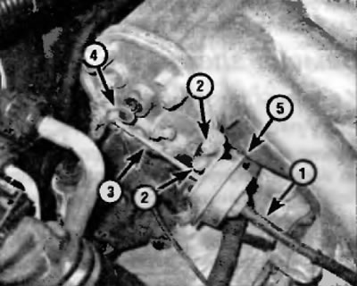
Pic. 15.18. Removing and installing the intake manifold actuator
1 - Vacuum supply hose (from VSV)
2 - fastening bolts
3 - Rod of the actuator
4 - Lever of the actuator
5 - Executive device
19. Release the E-clip (pic. 15.19), which secures the actuator stem to the actuator arm, and then disconnect the stem from the arm.
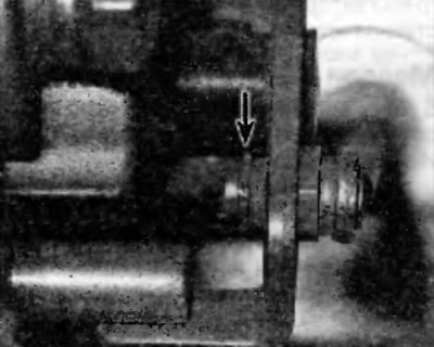
Pic. 15.19. To disconnect the intake manifold actuator rod from the actuator arm, use a small screwdriver to remove the E-clip
20. Turn out the corresponding bolts and remove the executive device.
21. Installation is carried out in the reverse order of removal.
Throttle body actuator
Application. The throttle body actuator is located on the underside of the throttle body. This actuator is only used on 1999-2003 models. On 2004 and later models with electronic throttle, this actuator is not used.
22. Remove the throttle body (see chapter 4).
23. Remove the screws securing the actuator (pic. 15.23) and remove the actuator from the throttle body.
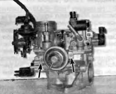
Pic. 15.23. To disconnect the air intake control valve actuator from the throttle body, remove the two bolts
24. Installation is carried out in the reverse order of removal.