
Attention! Gasoline is highly flammable. Therefore, additional precautions must be taken when working on any honor fuel system or EVAP system. Do not smoke or allow open flames or unprotected light fixtures near the work area. Do not work in rooms where gas appliances are present (e.g. water heaters or clothes dryers). Since gasoline is a carcinogen (contributes to the development of cancer), try not to allow fuel to come into contact with exposed areas of the body. Wear fuel resistant gloves. In case of contact with fuel on the skin, the affected area should be washed immediately with soap and water. Wipe up spilled fuel immediately and do not store fuel-soaked rags where they could ignite. Wear safety goggles when doing any work on the fuel system. Keep a class B fire extinguisher handy at all times.
Purge valve
Note. On four-cylinder models, the purge valve is mounted on the baffle behind the throttle body. On V6 models, the purge valve is located on a support bracket bolted to the front end of the intake manifold. The accompanying drawing in this paragraph shows the purge valve used on V6 models, but the purge valve used on four-cylinder models is similar except for its location.
11. Disconnect the ground wire from the battery (see paragraph 1 of chapter 5).
12. Remove the engine cover (in the presence of) (see paragraph «Intake manifold - removal and installation» in chapter 2).
13. Disconnect the purge valve electrical connector (pic. 19.13, a, b).
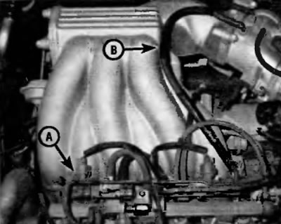
Pic. 19.13, a. On V6 models purge valve (A) for EVAP system (EVAP) located on a support bracket on the front side of the intake manifold. EVAP purge hose (IN) connects the metal tubing on the bracket to the throttle body
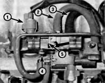
Pic. 19.13, b. Typical EVAP purge valve (V6 model shown). To shine the purge valve:
1 - Disconnect the electrical connector
2 - Disconnect the EVAP hose (coming from the EVAP canister)
3 - Disconnect the EVAP purge hose (to the metal piping on the support bracket which is connected to the throttle body by the purge hose shown in fig. 19.13.а)
4 - Remove the purge valve mounting element
5 - Remove purge valve from support bracket (on four-cylinder models, the bracket that is part of the purge valve is bolted to the bulkhead)
14. Disconnect the vacuum hoses from the purge valve.
15. Remove the screw (V6 models) or bolt (four-cylinder models) securing the purge valve and remove the valve.
16. Installation is carried out in the reverse order of removal.
All other elements (underneath the car)
17. Disconnect the ground wire from the battery (see paragraph 1 of chapter 5).
18. Raise the rear of the vehicle and place secure supports under it.
19. Remove the protective cover from the EVAP canister (pic. 19.19).
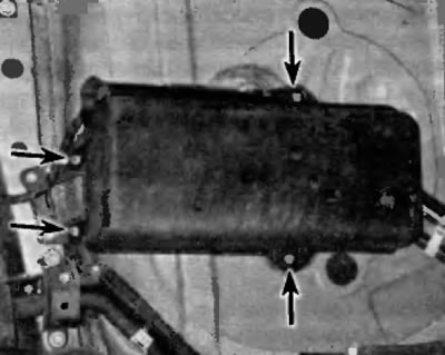
Pic. 19.19. To detach the protective cover from the EVAP canister, unscrew the nuts
Vacuum switching valve (VSV) for pressure switching valve
Note. The VSV valve for the pressure switching valve is located in the EVAP canister.
20. Disconnect the vacuum switch valve electrical connector (VSV) for pressure switching valve (pic. 19.20).
Pic. 19.20. Removal and installation of the valve of switching of vacuum (VSV) for pressure switching valve
21. Clearly tag the two EVAP hoses that connect the VSV to the pressure switch valve and to the EVAP canister, then disconnect both from the VSV.
22. Turn out the screw and remove the valve.
23. Installation is carried out in the reverse order of removal.
Air release valve
Note. The air release valve is located on the EVAP canister.
24. Disconnect the EVAP hoses from the air release valve (pic. 19.24).
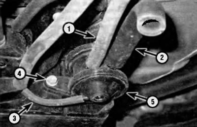
Pic. 19.24. Removal and installation of the valve of release of air
1 - Disconnect the EVAP inlet hose (to the canister shut-off valve on the air filter housing)
2 - Air release hose (you do not need to remove this hose to remove the bleed valve, but you must inspect it)
3 - EVAP connecting hose (between EVAP canister and air release valve)
4 — Bolt of fastening of the valve of release of air
5 - Air release valve
25. Turn out a bolt of fastening of the valve of release of air and remove the valve.
26. Installation is carried out in the reverse order of removal.
Pressure switching valve
Note. The pressure switching valve is located on the EVAP canister.
27. Disconnect VSV wiring harness from pressure switch valve support bracket (pic. 19.27).
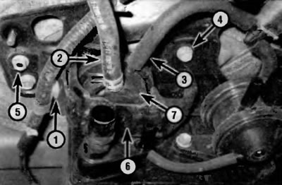
Pic. 19.27. Removal and installation of the pressure switching valve
1 - Using a small screwdriver, release the VSV harness clip from the pressure switch valve support bracket
2 - EVAP hose (to the fuel tank)
3 - EVAP connecting hose (between VSV and pressure switching valve)
4 - Bolt
5 - Nut
6 - Support bracket
6 - Pressure switching valve
28. Disconnect the EVAP hoses from the pressure switch valve.
29. Turn out a bolt and turn away a nut of fastening of a basic arm of the valve of switching of pressure and remove the valve of switching of pressure and a basic arm.
30. Installation is carried out in the reverse order of removal.
EVAP Adsorber
Note. The EVAP canister is located behind the underbody of the vehicle, behind the rear suspension cross member.
31. Disconnect the VSV valve electrical connector (pic. 19.20).
32. Disconnect the VSV harness from the pressure switch valve support bracket and disconnect the EVAP hoses from the canister (pic. 19.32. a, b).
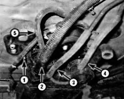
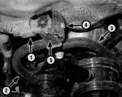
Pic. 19.32, a. Before removing the EVAP canister:
1 - Disconnect the VSV harness from the pressure switch valve support bracket
2 - Disconnect the EVAP vent hose (going to the fuel tank) (For installation details, see fig. 19.32, b)
3 - Disconnect the EVAP purge hose (to the purge valve in the engine compartment)
4 - Disconnect the EVAP air intake hose (to the canister shut-off valve on the air filter housing)
5 - Disconnect the EVAP hose (going to the fuel tank)
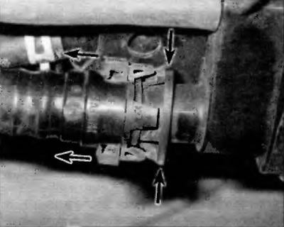
Pic. 19.32 b. To disconnect the EVAP vent hose fitting, press the locking tabs and then disconnect the connector in the tubing on the EVAP canister
33. Turn out bolts of fastening of a basic arm of an adsorber (rice 19.33) and remove the canister and associated support bracket as a unit.
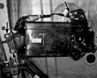
Pic. 19.33. To disconnect the EVAP canister, remove the three bolts
34. If the EVAP canister is being replaced, remove the VSV valve, bleed valve, and pressure switch valve from the canister (see p.p. 20-30), then detach the canister from its support bracket.
35. Installation is carried out in the reverse order of removal.