
- Lubricate the cylinder bore.
- Sort all connecting rods by cylinder numbers. Label "VORN" on the connecting rod and on the piston crown should be directed towards the engine pulleys.
- Distribute the joints of the piston rings around the circumference of the piston, as shown in Figure 315. Position the oil scraper ring, consisting of three parts, so that the locks are not located against each other.
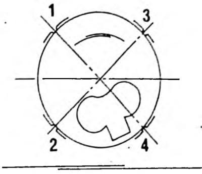
Pic. 315. Location of piston ring locks around the circumference of the piston.1. Upper compression ring; 2. Lower side ring of the oil scraper ring; 3. Upper side ring of the oil scraper ring; 4. Middle compression ring.
- Apply piston ring tightening tape where the piston rings are installed and press the rings into the grooves. Check that they are properly seated.
- Place short pieces of rubber or plastic hose onto the connecting rod studs to avoid scratching the cylinder bore. The nuts must always be replaced, since once installed, the nuts lose their fastening ability.
- Rotate the crankshaft until the two journals are at bottom dead center.
- Push the connecting rod into the hole from above. To do this, place the engine on its side so that the connecting rod can be guided along the bearing journals and does not scratch the cylinder bore or connecting rod journal. The connecting rod bearing shells should already be in the connecting rod, with their nose in the cutout.
- When pulling out, check again that the marks "VORN" positioned correctly relative to each other.
- Push in the piston until the piston rings are sequentially inserted into the cylinder and the connecting rod leg is seated on the shaft journal.
- Place the second bearing shell into the bearing cover and lubricate the shell. Place the cap on the connecting rod studs and tap lightly. Pieces of rubber hose must first be removed.
- Lubricate the surfaces of the nuts on the connecting rod bearing caps.
- Tighten the new brown nuts alternately to 65 Nm.
- After installing the connecting rod, rotate the crankshaft several times to immediately detect jamming.
- Rotate the crankshaft so that the other two axles are located at the bottom and install the remaining pistons and connecting rods in the same way.
- Check the position of all markings again and check that the pistons are installed correctly.
- Install a dial indicator on the cylinder block, as shown in Figure 21, and measure the play between the side surfaces of the connecting rod and the crankshaft, moving the connecting rod bearing by hand along the shaft journal in both directions. The axial play of the connecting rod bearing should not exceed 0.40 mm.
- To complete the assembly, install the oil pump, gears, front cover and oil pan.