
Note. Turn off the ignition (OFF) for 60 s before performing the following checks.
Checking the duration of operation of the control lamp for turning on glow plugs.
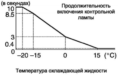
Pic. 7.16. Diagrams of the duration of the operation of the control lamp for turning on glow plugs
Check the duration of the control lamp (pic. 7.16).
Turn on the ignition (ON (IG)), and then measure the duration of the pilot lamp.
Switch off the ignition.
If the test result is not as described, check the engine ECU, engine coolant temperature sensor, glow plugs, and glow plug relay.
Note. The actual duration of the control lamp operation may differ slightly from the values shown in the diagram.
Checking the preheating system
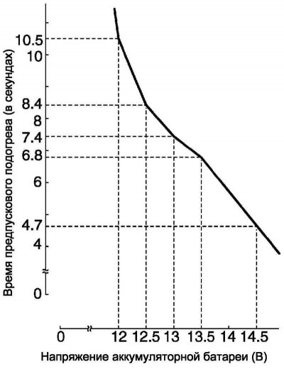
Pic. 7.17. Preheating time diagrams
Check preheat time (pic. 7.17).
Turn on the ignition (ON (IG)) and measure the time the battery voltage is applied to the glow plugs.
Switch off the ignition.
Verification conditions
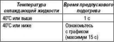
If the test result is not as described, check the engine ECU, engine coolant temperature sensor, glow plugs, and glow plug relay.
Turn on the ignition (STA) and check that voltage is being supplied from the battery to the glow plugs.
While turning the crankshaft, measure the time the battery voltage is applied to the glow plugs.
Verification conditions
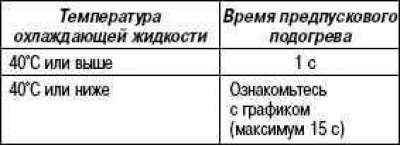
If the test result is not as described, check the engine ECU, engine coolant temperature sensor, glow plugs, and glow plug relay.
Postglow time check
Check postglow duration.
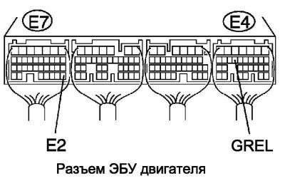
Pic. 7.18. Engine ECU Connector
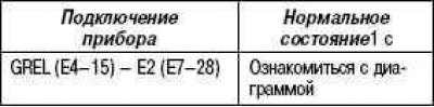
After starting the engine, measure the time the battery voltage is applied to the GREL terminal of the engine ECU (pic. 7.18).
Verification conditions
If the test result is not as described, check the engine ECU, engine coolant temperature sensor, glow plugs, and glow plug relay.
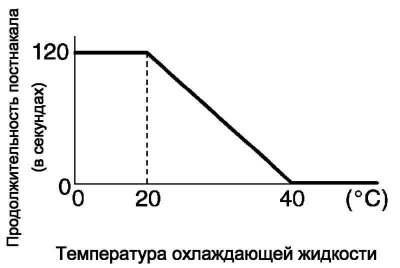
Pic. 7.19. Postglow time diagram
Checking glow plugs
Check resistance.
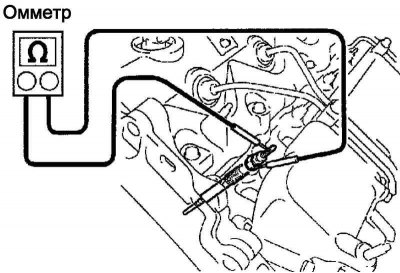
Pic. 7.20. Measuring resistance between glow plug terminal and ground
Using an ohmmeter, measure the resistance between the glow plug terminal and ground (pic. 7.20).
Verification conditions
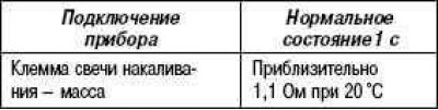
If the resistance is not within specification, the glow plug must be replaced.
Note. Damage to the insulating tubes can cause an open circuit or shorten the life of the glow plugs.
Note. When cleaning glow plugs, be careful not to get oil or gasoline on them.
Note. If during the check oil and cleaner are found on the terminals «Bakelite», wipe them off with a dry cloth.
Note. It is necessary to ensure that the voltage does not exceed 11 V, because. this may open the circuit.
Check of the relay of inclusion of glow plugs assy
Check resistance.
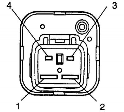
Pic. 7.21. Relay connector pins
Measure the resistance between the terminals with an ohmmeter (pic. 7.21).
Verification conditions
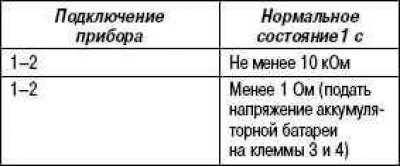
If the resistance is not within specification, the glow plug relay must be replaced.