
Generator disassembly
Loosen the nut and remove the terminal insulator.
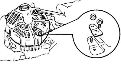
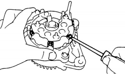
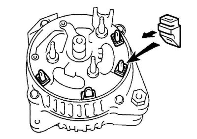
Pic. 7.42. Removing the rectifier plate
Remove the rectifier plate (pic. 7.42).
Unscrew the three cover fastening nuts and remove the generator cover from the side of the rectifier unit.
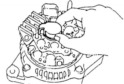
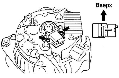
Pic. 7.43. Removing the brush holder cover
Remove the brush holder cover (pic. 7.43).
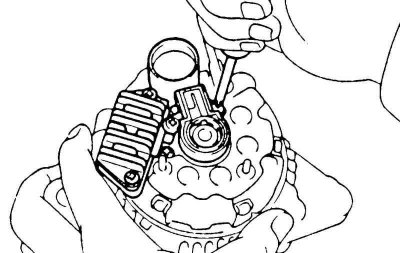
Pic. 7.44. Removing the brush holder and electronic voltage regulator
Unscrew five screws and remove the brush holder with cover and electronic voltage regulator (pic. 7.44).
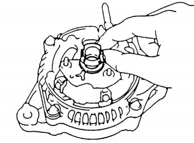
Pic. 7.45. Removing the sealing plate
Remove sealing plate (pic. 7.45).
Pic. 7.46. Removing the front cover of the generator
Unscrew the four screws, remove the rectifier unit, four rubber insulators and the front cover of the generator (pic. 7.46).
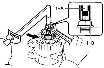
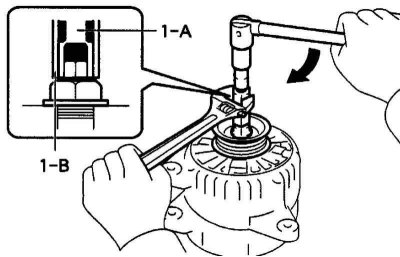
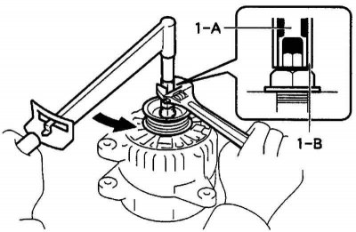
Pic. 7.47. Installation of special tools for removing the rotor shaft pulley
Install special fixtures «1-A» and «1-B» on the generator pulley. Holding a special tool «1-A» torque wrench, tighten the special tool «1-B» (clockwise) (pic. 7.47).
Tightening torque: 39 Nm.
Attention! Make sure the special tool «1-A» securely fixed to the rotor shaft.
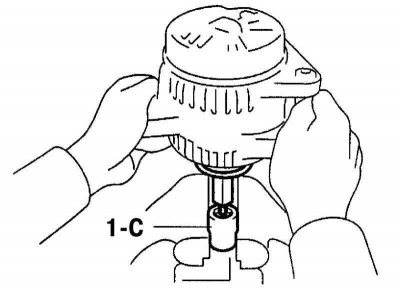
Pic. 7.48. Installing the generator on a special tool «1-C»
Clamp special tool «1-C», as shown in figure 7.48, and install a generator on it.
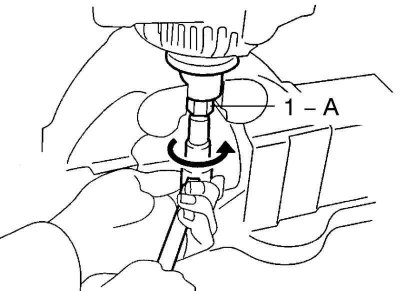
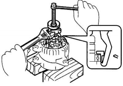
Pic. 7.49. Unscrewing the nut securing the alternator pulley with a special tool «1-A»
To loosen the pulley nut, turn the special tool «1-A» in the direction shown in Figure 7.49.
Attention! To avoid damage to the rotor shaft, unscrew the pulley fastening nut no more than half a turn.
Remove the alternator from the special tool «1-C».
Pic. 7.50. Removing special tools
Loosen the special tool «1-B» and remove the special tools «1-A» and «1-B» (pic. 7.50).
Loosen the pulley nut and alternator pulley.
Unscrew the bolt, three fastening nuts and remove the plate clamp and the rear cover of the generator.
Remove the brush holder cover.
Unscrew the two fastening screws and remove the brush holder.
Unscrew the three screws and remove the voltage regulator.
Unscrew the four screws and remove the lead insulator.
Remove the rubber insulator.
Remove the rectifier plate.
Unscrew the four nuts and remove the wiring clamp.
Pic. 7.51. Removing the rectifier
Using a bearing puller, remove the rectifier block (pic. 7.51).
Remove the washer and remove the rotor from the generator cover on the drive side.
Checking the voltage regulator relay
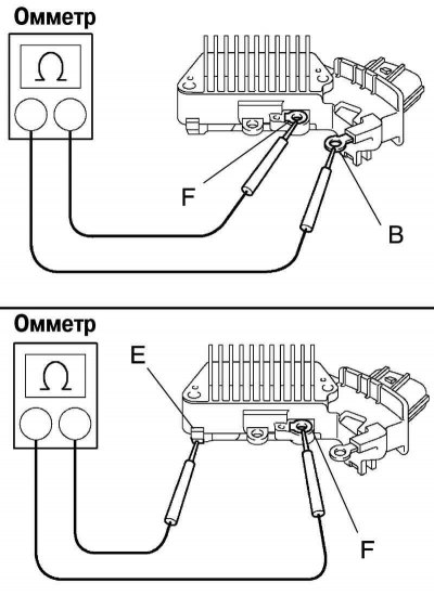
Pic. 7.52. Checking the voltage regulator relay
Using an ohmmeter, check continuity between diodes F and B (pic. 7.52).
Attention! When the positive and negative poles between terminals F and B are connected in a single circuit, conduction should be in only one direction. If there is continuity in both directions, one of the diodes may be broken. In this case, replace the voltage regulator.
Using an ohmmeter, check continuity between diodes F and E.
Rotor check
Check for an open in the field winding.
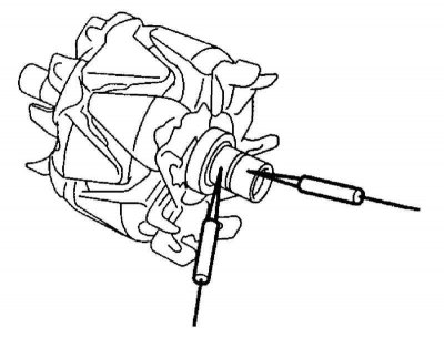
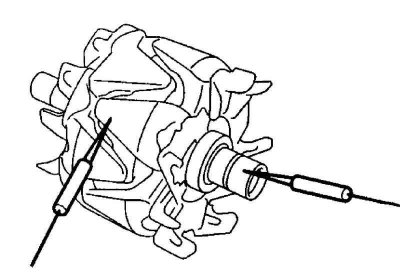
Pic. 7.53. Checking resistance between slip rings
Use an ohmmeter to measure the resistance between the slip rings (pic. 7.53).
Rated resistance (V «cold» able): 2.7-3.1 ohm.
If the resistance tends to infinity, i.e. circuit is open, replace the rotor.
Pic. 7.54. Checking the circuit of the field winding on «mass»
Check if there is a short circuit in the field winding «mass» (pic. 7.54).
Using an ohmmeter, measure the resistance between the rotor pole and the slip ring.
If resistance is 0 (circuit is closed), then replace the rotor.
Checking slip rings
Check the working surfaces of the slip rings. They should not have burrs or chips.
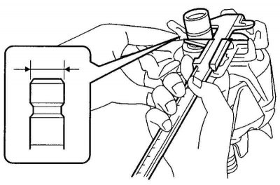
Pic. 7.55. Measuring the diameter of slip rings
Measure the diameter of the slip rings with a caliper (pic. 7.55).
- Standard diameter: 14.2-14.4 mm.
- Minimum allowable: 12.8 mm.
If the diameter of the slip rings is less than the minimum, the rotor must be replaced.
Checking the rectifier unit
Check the positive valve.
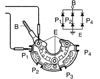
Pic. 7.56. Scheme for checking the conductivity of the contacts of the rectifier unit
Connect the negative probe of an ohmmeter to the positive terminal of the rectifier unit, and connect the positive probe in series to each of the other three terminals. Check for conductivity (closed circuit) in all three dimensions (pic. 7.56).
Reverse the polarity of the tester probes and repeat the first procedure. Make sure the circuit is open in all three dimensions (resistance tends to infinity).
Check negative valve.
Connect the positive probe of the ohmmeter to the negative terminal of the rectifier unit, and connect the negative probe in series to each of the other three terminals. Check for conductivity (closed circuit) in all three dimensions.
Reverse the polarity of the tester probes and repeat the first procedure. Make sure the circuit is open in all three dimensions (resistance tends to infinity).
If test conditions are not met, replace the rectifier unit.
Checking the brushes
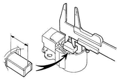
Pic. 7.57. Measuring the length of the protruding part of the brush
Measure the length of the protruding part of the brushes (pic. 7.57).
- Standard length: 9.5-11.5 mm.
- Minimum allowable: 1.5 mm.
If the brushes are less than the minimum length, replace the brushes and brush holder assembly.
Bearing check
Check the front bearing.
Check that the front bearing runs smoothly without binding.
Replace bearing if necessary.
Loosen the four screws and remove the bearing holder.
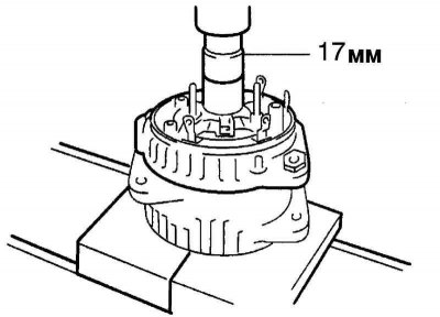
Pic. 7.58. Pressing out the front bearing
With a press and socket (17 mm) press in the front bearing (pic. 7.58).
Using a special punch, press the new front bearing into the drive side alternator cover.
Install the bearing holder and tighten the four screws securing it.
Tightening torque: 3 Nm.
Generator Assembly
Install the drive side generator cover onto the rotor.
Install the washer.
Install the rectifier housing with a plastic-headed hammer. Secure the housing with four nuts.
Tightening torque: 4.5–5.4 Nm.
Pic. 7.59. Installation of insulators
Install the four rubber insulators of the rectifier housing (pic. 7.59).
Attention! Install the insulators carefully, being careful not to damage them.
Install the terminal and sealing plate.
Install the rectifier unit by fixing it with four screws.
Tightening torque: 2.9 Nm.
Install the voltage regulator with four screws.
Tightening torque: 2.0 Nm.
Pic. 7.60. Installing the brush holder
Install the brush holder by securing it with two screws (pic. 7.60).
Tightening torque: 2.0 Nm.
Install the brush holder cover.
Install the rear cover and rectifier plate.
Install the terminal insulator by securing it with the nut.
Tightening torque: 4.1 Nm.
Install the pulley on the toe of the rotor shaft and hand-tighten the pulley nut.
Pic. 7.61. Installation of the rotor shaft pulley
Holding a special tool «1-A» torque wrench, tighten the special tool «1-B» (pic. 7.61).
Tightening torque: 39 Nm.
Check that the special tool «1-A» was securely fixed to the rotor.
Clamp special tool «1-C» in a vise and place the generator on it.
To tighten the pulley mounting nut, turn the special tool (1-A) clockwise.
Tightening torque: 111 Nm.
Remove the alternator from the special tool «1-C».
Loosen the special tool «1-B» and remove the special tools «1-A» and «1-B».
Make sure the rotor rotates smoothly without binding.