



Share information:
Car engine management system Corolla Verso 3 (AR10)

Ignition system 1ZZ-FE and 3ZZ-FE — design description
Fig. 2.26. Block diagram of the ignition system of 1ZZ-FE and 3ZZ-FE engines The engine is equipped with a system of ignition with individual coils (DIS). The use of DIS increases the accuracy of ignition timing,...
Fig. 2.26. Block diagram of the ignition system of 1ZZ-FE and 3ZZ-FE engines The engine is equipped with a system of ignition with individual coils (DIS). The use of DIS increases the accuracy of ignition timing,...
Engine Management System 1ZZ-FE and 3ZZ-FE — Design Description
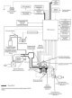
Design Fig. 2.30. Structural diagram of the engine control system Figure 2.30 shows the configuration of the electronic engine management system. Main components of the engine management system Fig. 2.31. Location of...
Design Fig. 2.30. Structural diagram of the engine control system Figure 2.30 shows the configuration of the electronic engine management system. Main components of the engine management system Fig. 2.31. Location of...

Engine Management System CD-FTV — Design Description
Fig. 2.93. 1CD-FTV engine control system diagram Fig. 2.94. Location of the main components of the 1CD-FTV engine control system General information The 1CD-FTV engine control system consists of the main components...
Fig. 2.93. 1CD-FTV engine control system diagram Fig. 2.94. Location of the main components of the 1CD-FTV engine control system General information The 1CD-FTV engine control system consists of the main components...

Checks without removing from the vehicle (1ZZ-FE / 3ZZ-FE)
Checking the variable valve timing control oil valve assembly Check the operation of the node. Connect the Hand-Held Diagnostic Tool II to the DLC3 diagnostic connector. Turn the ignition ON (IG). Turn on the Portable...
Checking the variable valve timing control oil valve assembly Check the operation of the node. Connect the Hand-Held Diagnostic Tool II to the DLC3 diagnostic connector. Turn the ignition ON (IG). Turn on the Portable...

Checks without removing from the vehicle (1CD-FTV)
Checking the mass air flow meter (using a portable diagnostic device II) Check the operation of the node. Connect the Hand-Held Diagnostic Tool II to the DLC3 diagnostic connector. Turn the ignition switch ON (IG) and...
Checking the mass air flow meter (using a portable diagnostic device II) Check the operation of the node. Connect the Hand-Held Diagnostic Tool II to the DLC3 diagnostic connector. Turn the ignition switch ON (IG) and...

Replacing the variable valve timing control oil valve (1ZZ-FE / 3ZZ-FE)
Disconnect the negative battery terminal. Remove the cylinder head cover for cylinder bank No.2. Removal Disconnect the variable valve timing control oil valve connector. Fig. 2.562. Connector and valve mounting bolt...
Disconnect the negative battery terminal. Remove the cylinder head cover for cylinder bank No.2. Removal Disconnect the variable valve timing control oil valve connector. Fig. 2.562. Connector and valve mounting bolt...

Replacing the mass air flow meter (1ZZ-FE / 3ZZ-FE)
Disconnect the negative battery terminal. Removal Disconnect the mass air flow meter connector. Fig. 2.564. Mass air flow meter Remove 2 bolts, then remove the mass air flow meter (fig. 2.564). Installation Install the...
Disconnect the negative battery terminal. Removal Disconnect the mass air flow meter connector. Fig. 2.564. Mass air flow meter Remove 2 bolts, then remove the mass air flow meter (fig. 2.564). Installation Install the...

Replacing the coolant temperature sensor (1ZZ-FE / 3ZZ-FE)
Disconnect the negative battery terminal. Drain the coolant. Remove the cylinder head cover for cylinder bank No.2. Removal Disconnect the engine coolant temperature sensor connector. Fig. 2.565. Removing the coolant...
Disconnect the negative battery terminal. Drain the coolant. Remove the cylinder head cover for cylinder bank No.2. Removal Disconnect the engine coolant temperature sensor connector. Fig. 2.565. Removing the coolant...

Replacing the knock sensor (1ZZ-FE / 3ZZ-FE)
Disconnect the negative battery terminal. Remove the lower engine shield No.1. Removal Disconnect the knock sensor connector. Fig. 2.566. Removing the knock sensor Loosen the mounting nut and remove the knock sensor...
Disconnect the negative battery terminal. Remove the lower engine shield No.1. Removal Disconnect the knock sensor connector. Fig. 2.566. Removing the knock sensor Loosen the mounting nut and remove the knock sensor...

Replacing the accelerator pedal assembly (1ZZ-FE / 3ZZ-FE)
Disconnect the negative battery terminal. Removal Disconnect the accelerator pedal position sensor connector. Fig. 2.568. Removing the accelerator pedal Remove 2 bolts, then remove the accelerator pedal (fig. 2.568)....
Disconnect the negative battery terminal. Removal Disconnect the accelerator pedal position sensor connector. Fig. 2.568. Removing the accelerator pedal Remove 2 bolts, then remove the accelerator pedal (fig. 2.568)....

Engine ECU Replacement (1ZZ-FE / 3ZZ-FE)
Disconnect the negative battery terminal. Remove the glove box lid assembly. Removal Disconnect the wiring harness clamp. Fig. 2.569. Engine ECU connectors Disconnect 4 engine ECU connectors (fig. 2.569). Fig. 2.570....
Disconnect the negative battery terminal. Remove the glove box lid assembly. Removal Disconnect the wiring harness clamp. Fig. 2.569. Engine ECU connectors Disconnect 4 engine ECU connectors (fig. 2.569). Fig. 2.570....
Removal and installation the throttle body (1CD-FTV)
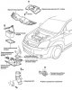
Fig. 2.573. Engine throttle assembly Fig. 2.574. Throttle assembly connectors Disconnect the negative battery terminal. Remove the upper radiator shroud. Drain the coolant. Remove the upper engine cover No.1. Remove the...
Fig. 2.573. Engine throttle assembly Fig. 2.574. Throttle assembly connectors Disconnect the negative battery terminal. Remove the upper radiator shroud. Drain the coolant. Remove the upper engine cover No.1. Remove the...

Replacing the mass air flow meter (1CD-FTV)
Disconnect the negative battery terminal. Disconnect the mass air flow meter connector. Fig. 2.576. Mass air flow meter Remove 2 bolts, then remove the mass air flow meter (fig. 2.576). Install a mass air flow meter....
Disconnect the negative battery terminal. Disconnect the mass air flow meter connector. Fig. 2.576. Mass air flow meter Remove 2 bolts, then remove the mass air flow meter (fig. 2.576). Install a mass air flow meter....

Replacing the coolant temperature sensor (1CD-FTV)
Disconnect the negative battery terminal. Remove the upper radiator shroud. Drain the coolant. Remove the upper engine cover No.1. Removal Fig. 2.577. Coolant temperature sensor connector Disconnect the coolant...
Disconnect the negative battery terminal. Remove the upper radiator shroud. Drain the coolant. Remove the upper engine cover No.1. Removal Fig. 2.577. Coolant temperature sensor connector Disconnect the coolant...

Replacing the intake air temperature sensor (1CD-FTV)
Disconnect the negative battery terminal. Remove the upper radiator shroud. Remove the upper engine cover No.1.
Disconnect the negative battery terminal. Remove the upper radiator shroud. Remove the upper engine cover No.1.

Removal the intake air temperature sensor in a diesel engine
Fig. 2.579. Bracket of the wiring harness of the intake air temperature sensor Disconnect the wiring harness from the bracket (fig. 2.579). Disconnect the intake air temperature sensor connector. Fig. 2.580. Removing...
Fig. 2.579. Bracket of the wiring harness of the intake air temperature sensor Disconnect the wiring harness from the bracket (fig. 2.579). Disconnect the intake air temperature sensor connector. Fig. 2.580. Removing...

Replacing the camshaft angle sensor (1CD-FTV)
Disconnect the negative battery terminal Remove the windshield wiper arm cover. Remove the front left windshield wiper arm and blade assembly. Remove the front right windshield wiper arm and blade assembly. Remove the...
Disconnect the negative battery terminal Remove the windshield wiper arm cover. Remove the front left windshield wiper arm and blade assembly. Remove the front right windshield wiper arm and blade assembly. Remove the...
Engine ECU Replacement (1CD-FTV)
Note: If a fault occurs and the engine ECU registers an incorrect injector correction code, the engine may start to jerk or idle rough. This may also cause engine failure and shorten the life of the engine. Note: When...
Note: If a fault occurs and the engine ECU registers an incorrect injector correction code, the engine may start to jerk or idle rough. This may also cause engine failure and shorten the life of the engine. Note: When...

Emission Control System (1ZZ-FE / 3ZZ-FE)
Checking the mixture correction system (when using the portable diagnostic device II) Connect the Portable Diagnostic Tool II to the DLC3 connector. Turn on the ignition (ON). Select the device mode: Powertrain/ Engine...
Checking the mixture correction system (when using the portable diagnostic device II) Connect the Portable Diagnostic Tool II to the DLC3 connector. Turn on the ignition (ON). Select the device mode: Powertrain/ Engine...

Emission Control System (1CD-FTV)
Visual inspection of hoses, connections and seals Check for cracks, leaks or damage. Fig. 2.586. Engine components to be tested Check the engine components shown in Figure 2.586 for leaks, cracks or other damage. Note:...
Visual inspection of hoses, connections and seals Check for cracks, leaks or damage. Fig. 2.586. Engine components to be tested Check the engine components shown in Figure 2.586 for leaks, cracks or other damage. Note:...

Replacing the heated oxygen sensor (1ZZ-FE / 3ZZ-FE)
Disconnect the negative battery terminal. Remove the cylinder head cover for cylinder bank No.2. Removal the heated oxygen sensor (row 1, sensor 1) Fig. 2.588. Sensor wire Disconnect the sensor connector and release the...
Disconnect the negative battery terminal. Remove the cylinder head cover for cylinder bank No.2. Removal the heated oxygen sensor (row 1, sensor 1) Fig. 2.588. Sensor wire Disconnect the sensor connector and release the...

Replacing the crankcase ventilation valve (1ZZ-FE / 3ZZ-FE)
Remove the cylinder head cover for cylinder bank No.2. Disconnect hose No.2 of the crankcase ventilation system. Removal Fig. 2.593. Crankcase ventilation system valve Using a 19mm socket wrench, remove the PCV valve...
Remove the cylinder head cover for cylinder bank No.2. Disconnect hose No.2 of the crankcase ventilation system. Removal Fig. 2.593. Crankcase ventilation system valve Using a 19mm socket wrench, remove the PCV valve...

Replacement of the solenoid valve No. 1 (1ZZ-FE / 3ZZ-FE)
Removal Disconnect the negative battery terminal. Fig. 2.595. Electrovacuum valve Remove the solenoid valve #1 (fig. 2.595). Disconnect the solenoid valve connector. Disconnect the wiring harness clamp. Disconnect fuel...
Removal Disconnect the negative battery terminal. Fig. 2.595. Electrovacuum valve Remove the solenoid valve #1 (fig. 2.595). Disconnect the solenoid valve connector. Disconnect the wiring harness clamp. Disconnect fuel...

Replacing the carbon adsorber (1ZZ-FE / 3ZZ-FE)
Removal Disconnect fuel vapor discharge hose No.1 from the adsorber. Disconnect fuel hose No.1 from the adsorber. Fig. 2.598. Removing the adsorber Remove the canister from the bracket (fig. 2.598). Installation Fig....
Removal Disconnect fuel vapor discharge hose No.1 from the adsorber. Disconnect fuel hose No.1 from the adsorber. Fig. 2.598. Removing the adsorber Remove the canister from the bracket (fig. 2.598). Installation Fig....

Checking the Exhaust Gas Recirculation System (1CD-FTV)
Note. If there is a malfunction that causes the exhaust gas recirculation system (EGR) to operate continuously, black or white smoke may escape from the engine exhaust pipe. Checking if the EGR valve is installed...
Note. If there is a malfunction that causes the exhaust gas recirculation system (EGR) to operate continuously, black or white smoke may escape from the engine exhaust pipe. Checking if the EGR valve is installed...

Replacing the EGR valve (1CD-FTV)
Remove the negative terminal from the battery. Remove the air filter assembly. Removal the EGR valve Fig. 2.602. EGR valve connector Disconnect the valve connector and the two hoses that go to it (fig. 2.602). Fig....
Remove the negative terminal from the battery. Remove the air filter assembly. Removal the EGR valve Fig. 2.602. EGR valve connector Disconnect the valve connector and the two hoses that go to it (fig. 2.602). Fig....

Checking the ignition system (1ZZ-FE / 3ZZ-FE)
Inspection of ignition coil and spark testing Check for DTCs. Note: If a DTC is detected, perform the troubleshooting procedure for that DTC. Make sure there is a spark. Remove the cylinder head cover for cylinder bank...
Inspection of ignition coil and spark testing Check for DTCs. Note: If a DTC is detected, perform the troubleshooting procedure for that DTC. Make sure there is a spark. Remove the cylinder head cover for cylinder bank...
This section is available on: russian, bulgarian, belarusian, ukrainian, serbian, croatian, romanian, polish, slovak, hungarian
Similar sections for other Toyota models
➥ Control system (petrol) Toyota RAV 4 XA20 (2000-2005)
➥ Control system Toyota Highlander 1 (2000-2007, petrol)
➥ Engine management systems Toyota Cruiser 100 (1998-2007)
➥ Control system (I4) Toyota Camry XV30 (2001-2006)
➥ Control system (petrol) Toyota Corona T190 (1992-1997)
Link in different formats to this article
TEXTHTMLBB Code
- General information
- User manual
- Start of movement
- Faults en route
- Maintenance
- Power unit
- Engine repair
- Lubrication system
- Cooling system
- Ignition system
- Supply system
- Fuel supply (carburetor)
- Fuel supply (injector)
- Diesel engine
- Exhaust system
- Transmission
- Clutch
- Manual gearbox
- Automatic gearbox
- Chassis, running gear
- Front suspension
- Rear suspension
- Steering
- Brake system
- Wheels and tires
- Body and interior
- Exterior (external elements)
- Interior (internal elements)
- Interior heating
- Electrical equipment
- Equipment and devices
- Power devices
- Lighting system
- Glass cleaners and washers
- General information
- User manual
- Power unit
- Petrol engines 1ZZ, 3ZZ
- Diesel engines 1СD-FTV
- Cooling system
- Lubrication system
- Fuel system
- Control system
- Exhaust system
- Transmission
- Clutch and drive shafts
- Mechanical gearbox
- Chassis, running gear
- Car suspension
- Steering
- Brake system
- Body and interior
- Exterior (external elements)
- Electrical equipment
- Power devices
- Electrical circuits