



Share information:
Gasoline engines 1ZZ-FE and 3ZZ-FE Corolla Verso 3 (AR10)

1ZZ-FE and 3ZZ-FE engines — general information
Equipped with WT-i electronic variable valve timing system, ignition system with individual coils, intelligent electronic throttle control system ETCS-i and plastic intake manifold, these engines are distinguished by...
Equipped with WT-i electronic variable valve timing system, ignition system with individual coils, intelligent electronic throttle control system ETCS-i and plastic intake manifold, these engines are distinguished by...

Features of engine design
Fig. 2.2. Valve timing of the 1ZZ-FE engine Fig. 2.3. Valve timing of the 3ZZ-FE engine Cylinder head cover Fig. 2.4. Cylinder head cover The cylinder head cover is made of high-strength aluminum alloy by die casting...
Fig. 2.2. Valve timing of the 1ZZ-FE engine Fig. 2.3. Valve timing of the 3ZZ-FE engine Cylinder head cover Fig. 2.4. Cylinder head cover The cylinder head cover is made of high-strength aluminum alloy by die casting...

Valve mechanism — design description
Fig. 2.11. Valve mechanism General information The stroke of the valve tappets has been increased, a design without adjusting washers and with an increased contact surface with the cam has been used. High power, low...
Fig. 2.11. Valve mechanism General information The stroke of the valve tappets has been increased, a design without adjusting washers and with an increased contact surface with the cam has been used. High power, low...

Launch system — design description
Starter Fig. 2.27. Starter Instead of the pole windings used in a conventional starter, a planetary gear starter uses interpole magnets. The interpolar magnets are arranged so that the total magnetic flux increases and...
Starter Fig. 2.27. Starter Instead of the pole windings used in a conventional starter, a planetary gear starter uses interpole magnets. The interpolar magnets are arranged so that the total magnetic flux increases and...

Attachment drive — design description
Fig. 2.29. Drive of mounted units A single serpentine poly V-belt is used to drive the engine's auxiliary equipment. This design solution made it possible to reduce the length and weight of the engine, as well as to...
Fig. 2.29. Drive of mounted units A single serpentine poly V-belt is used to drive the engine's auxiliary equipment. This design solution made it possible to reduce the length and weight of the engine, as well as to...

Checking the ignition timing angle
Note: Turn off all electrical equipment and air conditioning. Note: Check the ignition timing with the cooling system fan turned off. Note: When checking the ignition timing, set the gear shift lever to neutral....
Note: Turn off all electrical equipment and air conditioning. Note: Check the ignition timing with the cooling system fan turned off. Note: When checking the ignition timing, set the gear shift lever to neutral....
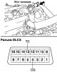
Checking without a diagnostic device
Remove the cylinder head cover. Fig. 2.113. Connecting the strobe sensor Set the strobe sensor to the position shown in Fig. 2.113. Note: Use a strobe that detects the first signal. Note: After checking, wrap the wire...
Remove the cylinder head cover. Fig. 2.113. Connecting the strobe sensor Set the strobe sensor to the position shown in Fig. 2.113. Note: Use a strobe that detects the first signal. Note: After checking, wrap the wire...

Checking the idle speed
Note: Turn off all electrical equipment and air conditioning. Note: Check the idle speed with the cooling fan turned off. Note: When checking the idle speed, place the gear shift lever in neutral. Checking with...
Note: Turn off all electrical equipment and air conditioning. Note: Check the idle speed with the cooling fan turned off. Note: When checking the idle speed, place the gear shift lever in neutral. Checking with...

Checking the compression in the cylinders
Warm up and turn off the engine. Remove the cylinder head cover of cylinder bank No.2. Remove 4 ignition coils. Remove 4 spark plugs. Disconnect 4 injector connectors. Fig. 2.115. Installing the compression gauge Insert...
Warm up and turn off the engine. Remove the cylinder head cover of cylinder bank No.2. Remove 4 ignition coils. Remove 4 spark plugs. Disconnect 4 injector connectors. Fig. 2.115. Installing the compression gauge Insert...

Checking the content of carbon monoxide and hydrocarbons in exhaust gases
Note: The content of carbon monoxide and hydrocarbons in the exhaust gases is regulated by the engine ECU. Start the engine. Let the engine run at 2500 min⁻¹ for approximately 180 s. Insert the gas analyzer probe at...
Note: The content of carbon monoxide and hydrocarbons in the exhaust gases is regulated by the engine ECU. Start the engine. Let the engine run at 2500 min⁻¹ for approximately 180 s. Insert the gas analyzer probe at...

Replacing the V-belt of the fan and generator
Note: Due to the use of an automatic belt tensioner in the design, it is not necessary to check the belt tension. Removal Remove the lower left engine shield. Remove the lower engine shield No.1. Remove the lower right...
Note: Due to the use of an automatic belt tensioner in the design, it is not necessary to check the belt tension. Removal Remove the lower left engine shield. Remove the lower engine shield No.1. Remove the lower right...

Adjusting the valve clearance
Checking valve drive clearances Remove the cylinder head cover. Set the piston of cylinder No.1 to TDC of the compression stroke. Fig. 2.118. Valves to be tested Check the valves shown in Figure 2.118. Using a set of...
Checking valve drive clearances Remove the cylinder head cover. Set the piston of cylinder No.1 to TDC of the compression stroke. Fig. 2.118. Valves to be tested Check the valves shown in Figure 2.118. Using a set of...
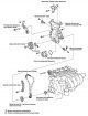
Timing chain replacement
Fig. 2.121. Timing chain components The components of the timing chain are shown in Fig. 2.121. Removal the right engine mount cushion Fig. 2.122. Fuel return pipe bracket mounting bolt Remove the bolt, then disconnect...
Fig. 2.121. Timing chain components The components of the timing chain are shown in Fig. 2.121. Removal the right engine mount cushion Fig. 2.122. Fuel return pipe bracket mounting bolt Remove the bolt, then disconnect...

Removal and installation camshafts
Fig. 2.157. Components of camshafts Remove the cylinder head cover. Set the piston of cylinder No.1 to TDC of the compression stroke. Removal camshaft #2 Fig. 2.158. Places of application of the camshaft chain and drive...
Fig. 2.157. Components of camshafts Remove the cylinder head cover. Set the piston of cylinder No.1 to TDC of the compression stroke. Removal camshaft #2 Fig. 2.158. Places of application of the camshaft chain and drive...

Replacing the timing chain or belt drive cover seal
Remove the lower engine shield No.1. Remove the lower right engine shield. Remove the cylinder head cover for bank 2. Remove the fan and alternator V-belt. Remove the crankshaft pulley. Use a knife to cut the working...
Remove the lower engine shield No.1. Remove the lower right engine shield. Remove the cylinder head cover for bank 2. Remove the fan and alternator V-belt. Remove the crankshaft pulley. Use a knife to cut the working...

Removal the power unit
Reduce the pressure in the fuel system. Disconnect the negative battery terminal. Remove the battery. Remove the battery tray. Fig. 2.183. Battery platform mounting bolts Remove the 4 mounting bolts, then remove the...
Reduce the pressure in the fuel system. Disconnect the negative battery terminal. Remove the battery. Remove the battery tray. Fig. 2.183. Battery platform mounting bolts Remove the 4 mounting bolts, then remove the...

Replacing the cylinder head gasket
Reduce the pressure in the fuel system. Remove the clamp from the main wiring harness in the engine compartment. Fig. 2.198. Fastening the upper outer panel of the hood Remove 7 mounting bolts and remove the upper outer...
Reduce the pressure in the fuel system. Remove the clamp from the main wiring harness in the engine compartment. Fig. 2.198. Fastening the upper outer panel of the hood Remove 7 mounting bolts and remove the upper outer...

Cylinder head overhaul
Fig. 2.218. Cylinder head components Removal the tapered threaded plug No.2 Fig. 2.219. Conical threaded plug Using a 10 mm Allen key, unscrew the tapered threaded plug and remove the gasket (fig. 2.219). Removal the...
Fig. 2.218. Cylinder head components Removal the tapered threaded plug No.2 Fig. 2.219. Conical threaded plug Using a 10 mm Allen key, unscrew the tapered threaded plug and remove the gasket (fig. 2.219). Removal the...
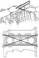
Checking the cylinder block for deformation
Fig. 2.282. Checking the cylinder block for warpage Using a precision straight edge and feeler gauge, measure the warpage of the cylinder head gasket mating surfaces (fig. 2.282). Maximum permissible warpage: 0.05 mm....
Fig. 2.282. Checking the cylinder block for warpage Using a precision straight edge and feeler gauge, measure the warpage of the cylinder head gasket mating surfaces (fig. 2.282). Maximum permissible warpage: 0.05 mm....
This section is available on: russian, bulgarian, belarusian, ukrainian, serbian, croatian, romanian, polish, slovak, hungarian
Similar sections for other Toyota models
➥ Gasoline engines Toyota Carina T170 (1988-1992)
➥ Petrol engines Toyota Cruiser 100 (1998-2007)
➥ Petrol engines (since 2001) Toyota RAV 4 XA20 (2000-2005)
Link in different formats to this article
TEXTHTMLBB Code
- General information
- User manual
- Start of movement
- Faults en route
- Maintenance
- Power unit
- Engine repair
- Lubrication system
- Cooling system
- Ignition system
- Supply system
- Fuel supply (carburetor)
- Fuel supply (injector)
- Diesel engine
- Exhaust system
- Transmission
- Clutch
- Manual gearbox
- Automatic gearbox
- Chassis, running gear
- Front suspension
- Rear suspension
- Steering
- Brake system
- Wheels and tires
- Body and interior
- Exterior (external elements)
- Interior (internal elements)
- Interior heating
- Electrical equipment
- Equipment and devices
- Power devices
- Lighting system
- Glass cleaners and washers
- General information
- User manual
- Power unit
- Petrol engines 1ZZ, 3ZZ
- Diesel engines 1СD-FTV
- Cooling system
- Lubrication system
- Fuel system
- Control system
- Exhaust system
- Transmission
- Clutch and drive shafts
- Mechanical gearbox
- Chassis, running gear
- Car suspension
- Steering
- Brake system
- Body and interior
- Exterior (external elements)
- Electrical equipment
- Power devices
- Electrical circuits