
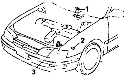
Location of electrical elements (A241L): 1 - overdrive switch, 2 - overdrive solenoid valve, 3 - engine start inhibit switch.
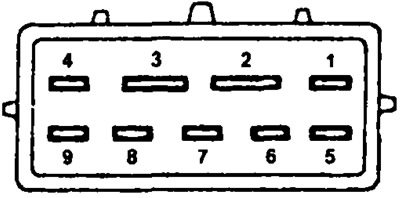
1. Check the start inhibit switch.
Check continuity between the connector pins shown in the table in each selector position.
| Selector position | conclusions |
| P | 2-8 6-1 |
| R | 6-5 |
| N | 2-3 6-7 |
| D | 6-8 |
| 2 | 6-9 |
| L | 6-4 |
2. Check the overdrive solenoid valve.
- A) Disconnect the valve connector.
- b) Measure resistance between leads "1" And "3". Rated resistance 11-15 Ohm.
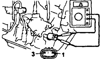
- V) When submitting conclusions "1" And "3" connector of the battery voltage solenoid valve, you should hear the click of the activated valve. If there is no click, replace the valve.
- G) Connect the solenoid valve connector.
3. Check the overdrive switch.
- A) Remove the center console.
- b) Use an ohmmeter to check the continuity between the terminals "1" And "3" switch connector. When the mode is on, there should be no conductivity, when it is off, there should be conductivity, otherwise replace the switch.
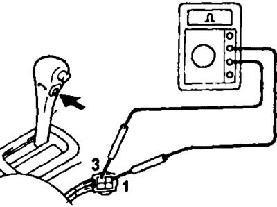
- V) Install the center console.