
Attention! Wait until the engine has completely cooled down before starting this procedure.
Note. 2004 and later vehicles are fitted with exhaust manifolds with catalytic converters, while 2003 and earlier vehicles are fitted with separate catalytic converters.
1. Disconnect the ground wire from the battery (see paragraph 1 of chapter 5).
2. Apply penetrating oil to the exhaust manifold mountings and let it soak in.
3. If you shoot the rear (close to the barrier) exhaust manifold, raise the front of the car and place it on reliable supports, then remove the lower engine protection (pic. 6.3, a, b).
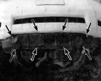
Pic. 6.3a. Arrangement of elements of fastening of the bottom protection of the engine (Hightlander)
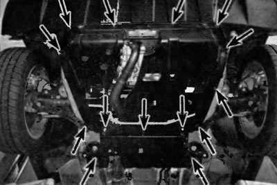
Pic. 6.3b. Location of the fastening elements of the main and rear sections of the lower protection (RX 300/330)
Attention! If the vehicle is equipped with electronically controlled air suspension, turn off the suspension height control switch.
4. Remove from manifold (ov) heated oxygen sensors (see chapter 6).
5. Turn out bolts and remove a heat-shielding screen over a final collector (in the presence of) (pic. 6.5).
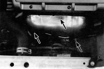
Pic. 6.5. Turn out bolts of fastening of a heat-shielding screen of system of release (The heat shield is not available on all models!
6. Remove the exhaust manifold tie (in the presence of) (fig 6.6).
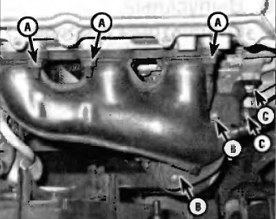
Pic. 6.6. An arrangement of nuts of fastening of a forward final collector (A), nuts of a flange of system releases (IN) and tie bolts (WITH) (lower exhaust manifold mounting nuts not visible)
7. Turn away nuts of fastening of an exhaust pipe (pipes) to exhaust manifold (am).
8. Turn out bolts of fastening of a final collector (ov) to the head (am) cylinders. moving from the edges to the middle. Remove manifold (s) from studs.
9. Carefully inspect the collector (s) and fasteners for cracks and damage.
10. Use a scraper to remove all traces of the old gasket material and carbon deposits from the mating surfaces of the cylinder head and manifold. If the gasket is leaking, check the surface of the manifold mating with the cylinder head for deformation. To do this, attach a straight, hard ruler to the surface to be measured and try to insert the probe. If the clearance exceeds the limit specified in Specifications at the beginning of this chapter, regrind the mating surface of the manifold, for which you should contact a service station.
11. Install a new gasket, guided by the studs on the cylinder head.
12. Install manifold (s) and tighten the nuts
13. Working from the center outwards and tighten the nuts three or four stages to the prescribed torque given in Specifications at the beginning of this chapter.
14. Reinstall the remaining elements, working in the reverse order of removal. Use new gaskets when connecting exhaust pipes.
15. Start the engine and check for leaks in the exhaust system.