
Attention! Wait until the engine has completely cooled down before starting this procedure.
Removing
1. Disconnect the ground wire from the battery (see paragraph 1 of chapter 5).
2. Drain the coolant from the cooling system, including the cylinder block (see chapter 1).
3. Remove the upper and lower intake manifolds (see paragraph 5).
4. Remove the exhaust manifold (s) (see paragraph 6).
5. Remove generator (see chapter 5). Remove the bolts and move the power steering pump to the side (refer to chapter 10).
6. Remove the timing belt, camshaft pulleys and upper intermediate pulley (see paragraph 7).
7. Turn out bolts of fastening of a back cover of a timing belt and remove it from the block of cylinders and heads of cylinders.
8. Disconnect the coolant sensor electrical connectors and remove the coolant distribution housing (pic. 11.8).
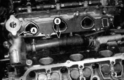
Pic. 11.8. Turn out bolts and remove the case of distribution of a cooling liquid (A), connecting hose (IN) should be replaced every time the intake manifold is removed
9. Remove the camshafts (s) from the head (OK), which (s) you intend to withdraw (see paragraph 10). Disconnect the electrical connectors for the camshaft position sensor and the VVT oil control valve (see paragraph 8).
10. Turn out bolts in a back part of heads of cylinders and shift plaits of electroconducting of the engine aside from heads.
11. Using a hex bit or 8mm socket wrench, remove the appropriate bolts (one in each head) (pic. 11.11).
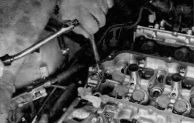
Pic. 11.11. Loosen the bolt with an 8mm hex bit
12. Using a 12-point socket, loosen the remaining cylinder head bolts ¼ turn per approach until they can be unscrewed by hand. Unscrew and remove them together with the hardened washers. Follow the reverse of the recommended tightening sequence (pic. 11.23).
13. Remove the cylinder head from the cylinder block. If the head does not come off, place a block of wood against it and hit the block with a hammer.
Warning. Do not insert any makeshift levers between the head and cylinder block. This can damage the sealing surfaces and result in leaks.
14. If necessary, repeat the procedure for another head.
Installation
15. Before installing the heads, the mating surfaces of the heads and cylinder blocks should be thoroughly cleaned.
16. Use a scraper to remove all traces of carbon and old gasket materials, and then clean the mating surfaces with lacquer thinner or acetone. If there is oil on the mating surfaces when the cylinder head is installed, the gasket may not seal properly and leakage will occur. When working on the block, pack the cylinders with a clean rag to prevent dirt from entering them. Use a vacuum cleaner to remove dirt that has entered the cylinders.
17. Check mating surfaces of the block and cylinder head for nicks, deep scratches and other damage. If the damage is minor, it can be repaired with a file; if it is large, machining may be the only option.
18. Using a tap of the proper size, calibrate the threads in the holes for the cylinder head bolts, then blow out the holes with compressed air. Check that nothing is left in the holes.
Attention! Always wear eye protection when working with compressed air.
19. Clamp each bolt in a vise and «drive away» die thread to remove any traces of corrosion and restore the thread. Dirt, corrosion products, sealant and damaged threads affect the tightening torque. Measure the diameter of the head shoulder area of each bolt and screw the results to the value given in Specifications at the beginning of this chapter. Replace any bolts that are too long.
20. Install new gaskets, referring to the dowel pins in the block (pic. 11.20).
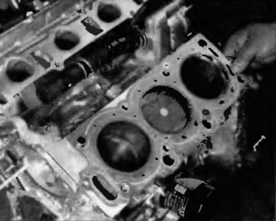
Pic. 11.20. Install new cylinder head gaskets with correct side up (check the alignment of all coolant hole and vinyls), focusing on the pins of the block
21. Accurately establish a head of cylinders not the block, without shifting a lining.
22. Apply some clean engine oil to the threads before installing the cylinder head bolts.
23. Screw in the bolts according to their original position and hand-tighten. Following the recommended sequence, tighten the bolts to the specified torque specified in Specifications at the beginning of this chapter (pic. 11.23). Do not tighten the hexagon socket head bolt at this stage.
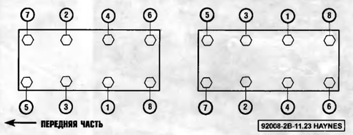
Pic. 11.23. Cylinder head bolt tightening sequence
24. Mark the front face of each bolt head with paint. Alternatively, you can mark the socket you are using.
25. Following the same sequence, tighten each hex bolt an additional ¼ turn (90°) (pic. 11.23).
26. Tighten the hexagon socket head bolt to the specified torque specified in Specifications at the beginning of this chapter.
27. Repeat the entire procedure to install the other cylinder head.
28. The rest of the installation is carried out in the reverse order of removal.
29. Fill the cooling system. Change engine oil and filter (see chapter 1). Start the engine and check for leaks.