
Application. Before starting this procedure, prepare two M6 x 1.0 mm bolts with a length of 16 to 20 mm. They are referred to in the text as technology bolts.
Removing
1. Set the engine to TDC (see paragraph 3), then remove the cylinder head covers (see paragraph 4), timing belt and camshaft pulleys (see paragraph 7).
2. The description in the following paragraphs refers to the removal of each of the four camshafts. Not every cylinder head first fixes the exhaust camshaft sub gear, removes the intake camshaft, and then the exhaust camshaft.
3. Align the timing marks on the camshafts on the drive and driven gears (pic. 10.3).
Note. On the right (rear) cylinder head, align the two dots on the intake camshaft gear with the two dots on the exhaust camshaft gear. On the left (front) cylinder head, align one dot on the intake camshaft gears with one dot on the exhaust camshaft gears.
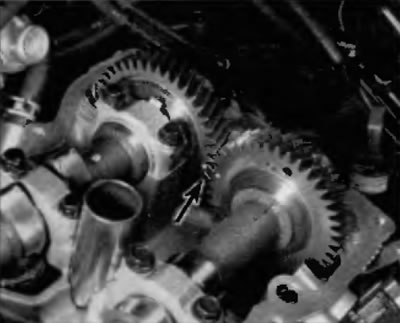
Pic. 10.3. Alignment marks on the reverse side of the distribution board gears (typical labels)
4. Fix the exhaust camshaft sub gear relative to the driven gear with a technological bolt screwed into the provided technological hole (pic. 10.12).
Warning. Since the axial clearances of the camshafts are minimal, the camshafts must be kept in a horizontal position when they are removed. If this is not followed, the area of the cylinder head next to the camshaft gears may be cracked or damaged due to gear engagement. Before removing the camshaft from the head, make sure that the torsional spring force from the auxiliary gear is eliminated with a service bolt.
5. Loosen the intake camshaft bearing cap bolts ¼ turn per approach until they can be unscrewed by hand. Start with the outer covers and move on to the inner ones.
6. Remove the bearing caps and carefully remove the intake camshaft. Keep it horizontal.
7. Loosen the exhaust camshaft bearing cap bolts ¼ turn per approach until they can be unscrewed by hand. Start with the outer covers and move on to the inner ones.
8. Remove the exhaust camshaft bearing caps and collar and carefully remove the exhaust camshaft. Keep it horizontal.
9. Repeat these steps on the other cylinder head.
10. Store the bearing caps by laying them out in the correct order.
Application. Now, if necessary, you can remove the pushers and valve shims with a magnetic tool. They should be stored separately so that they can be installed in their original places (pic. 10.10).
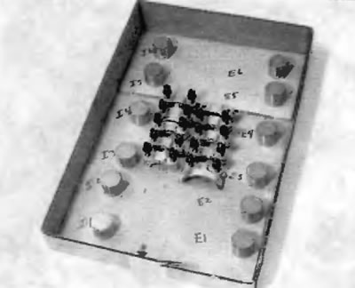
Pic. 10.10. Label the sled box for storing tappets/gaskets and camshaft bearing caps. Use a separate box for each set and mark the front (arrow), inlet (I) and release (E).
11. To remove the gear from the exhaust camshaft, place the shaft in a vice on the large hex section.
12. Insert the second technological bolt into the non-threaded hole along the auxiliary camshaft gear. Rest with a screwdriver on the newly installed technological bolt, turn the auxiliary gear clockwise and unscrew the first technological bolt. The second bolt is not required if you have a 2-prong wrench (pic. 10.12).
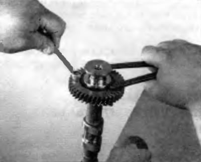
Pic. 10.12. Clamp the camshaft in a vice on the hex section using a 2-prong wrench, release the tension from the auxiliary gear and remove the service bolt, and then release the auxiliary gear
13. Remove the auxiliary gear circlip (pic. 10.13).
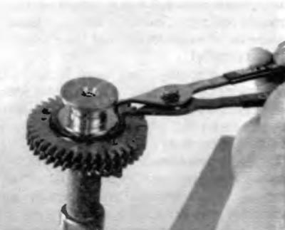
Pic. 10.13. Remove the retaining ring using special pliers
14. The bent washer, sub gear and camshaft gear spring can now be removed from the exhaust camshaft (pic. 10.14). Keep the rear camshaft components separate from the front camshaft components. At the front end of the intake camshaft is a VVT actuator, which is secured to the shaft with a large nut. To remove the VVT block, clamp the camshaft in a vice on the hex section and use an extension and a 46mm socket.
Note. The nut has a left-hand thread. Do not unscrew the nut or remove the VVT block unless you are going to replace the camshaft or VVT block.
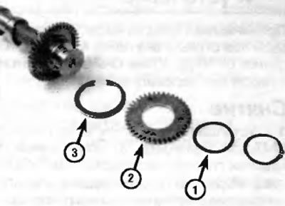
Pic. 10.14. Remove bent washer (1), auxiliary camshaft gear (2) and gear spring (3) (showed the exhaust camshaft)
Inspection
15. For a description of the procedures for inspecting camshafts, tappets and related components, refer to Chapter 2A. Refer to the Specifications at the beginning of this chapter.