
Note. Problems in the VVT oil control valve electrical circuit cause a DTC to be generated and a warning lamp to illuminate on the instrument panel «Check engine» (check engine). See Chapter B for information on fault codes.
Note. Most problems with the VVT system are caused by the oil control valve (ami) and the corresponding filter (ami). This valve requires regular engine oil and filter changes to keep it running smoothly. Some checks and inspections of the VVT system require the removal of the cylinder head cover and intake camshaft.
Oil Pilot Filter
8. Blockage of the strainer of the control oil valve (OCV) very often causes problems in the operation of the VVT system. Remove the filter from the rear of the cylinder head and inspect it for blockage. If necessary, clean the filter and reinstall it using a new O-ring. The larger end of the filter must face the head (pic. 8.8). Tighten the filter plug to the specified torque as specified in Specifications at the beginning of this chapter.
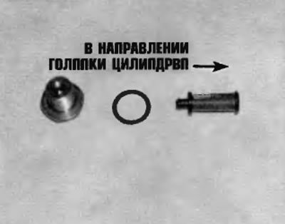
Pic. 8.8. When installing the filter, use a new O-ring and make sure that the large filter head faces the cylinder head
Control oil valve
9. To replace the oil control valve (OCV) unscrew the retaining bolt and remove the valve from the cylinder head (pic. 8.9, a, b). The valve is located on the rear side of each cylinder head (closer to the gear). When installing a new valve, use a new O-ring. Tighten the valve bolt to the specified torque specified in Specifications at the beginning of this chapter.
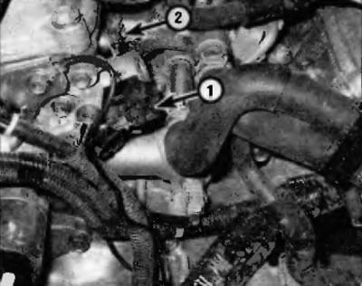
Pic. 8.9, a. The location of the control oil valves for the rear row of cylinders
1 - Electrical connector
2 - Bolt
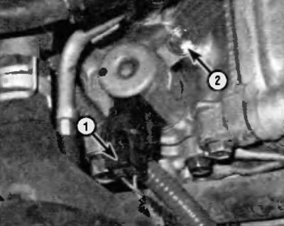
Pic. 8.9, b. The location of the control oil valves for the front row of cylinders
1 - Electrical connector
2 - Bolt
Camshaft pulley assembly with actuator
10. Remove the cylinder head cover (see paragraph 4), belt gas distribution mechanism (see paragraph 7) and intake camshaft (see paragraph 10).
Note. Do not remove the exhaust camshaft or sprocket from the vehicle.
11. Clamp the camshaft in a vise on a workbench. To clamp the shaft follows the hex section of the shaft.
Warning. Be careful not to damage the camshaft, its balls and necks.
12. Make sure that the toothed pulley assembly with the actuator does not turn from a fixed position. The fixed position is the neutral position that the actuator assumes when the engine is running at idle and no load, and also at any time when the VVT system is not activated by the PCM
13. Use a brake cleaner to remove all traces of oil from the front shaft journals and from the VVT oil control ports. Apply vinyl tape to all control holes except for the oil port on the advance side.
14. Apply air pressure 1.0kg/cm3 into the oil port on the advance side and try to turn the actuator by hand. The actuator should rotate freely without obvious binding by approximately 30 degrees in the advance direction from the detent position.
Note. It is imperative that there be an airtight seal between the air gun tip and the advance oil port pin because if there is an air leak at the air gun tip or any other oil control port, the locking pin in the actuator will not come out of the locating hole. If a leak occurs, apply slightly more air pressure to the advance side oil port to force the lock pin out of the mounting hole.
15. If the actuator does not rotate as freely as prescribed, replace the intake camshaft sprocket assembly with the actuator,
16. To replace the gear pulley assembly with the actuator, clamp the camshaft in a vise on a workbench and unscrew the nut by 46 mm by turning it clockwise (the nut has a left-hand thread).
17. Remove the toothed pulley assembly with the actuator. If the element cannot be removed from the camshaft, lightly tap it with a plastic-faced hammer.
Warning. Do not attempt to disassemble the toothed pulley assembly with the actuator. This is a non-separable unit, it is impossible to assemble it again.
18. Lubricate the bearing surface for the toothed pulley assembly with the actuator on the camshaft with clean engine oil. Align the locking pin before installing the timing pulley assembly with the actuator (in the camshaft) and a groove for the locking pin (in a toothed pulley assembled with an actuator). Install the toothed pulley assembly with the actuator. Screw on a new toothed pulley nut and tighten it to the specified torque specified in Specifications at the beginning of this chapter (do not forget that the nut has a left-hand thread).
19. Install the intake camshaft (see paragraph 10), belt gas distribution mechanism (see paragraph 7) and cylinder head cover (see paragraph 4).