



Caution! The models described in this manual are equipped with airbags. Always lock the SRS when you are going to work in the immediate vicinity of its components to prevent the possibility of accidental deployment of the airbag(s), which could result in serious injury (see chapter 12).
Caution! Fuel is extremely flammable, so take special precautions when working on any part of the fuel system. Do not smoke or use open flames or portable electric lighting devices that are not equipped with protective screens. Do not work in a garage that uses gas-powered equipment, such as a water heater or clothes dryer. Since fuel is carcinogenic, wear protective gloves when working to avoid contact with the fuel on your hands. If fuel comes into contact with your skin, wash it off immediately with soap and water. Any fuel spilled on the floor must be wiped up immediately. Do not store contaminated rags left over from working with fuel in areas where ignition is possible. The fuel system of gasoline engines maintains constant pressure. If you are going to disconnect any fuel line, you must first relieve the pressure (more information can be found in chapter 4A). When performing any work on the fuel system, wear safety glasses or a mask and keep a fire extinguisher handy.
Note: Removing an engine is a fairly complex job, especially for a non-professional doing it in your own garage. Based on the design features of the vehicle, the manufacturer requires that the engine and gearbox assembly be removed from underneath the vehicle (but not from above). A jack and safety stands alone won't do - the car will need to be raised quite high. This requires a two-post vehicle lift and a height-adjustable powertrain support, as recommended by the manufacturer.
Removal
1. Place the vehicle on a frame lift and position the lift arms under the jack sockets (see section "Raising the car with a jack and installing safety supports").
2. In gasoline engines, relieve the pressure in the fuel system (see chapter 4A).
3. Disconnect the negative battery terminal, cover the fenders and front panel with protective covers and remove the hood (see chapter 11).
4. Remove the air filter assembly (see chapter 4A or 4B). Also disconnect the accelerator cable, where possible, remove it together with the bracket from the engine and move it to the side.
5. Remove the plastic panel under the windshield and the ventilation system drain (see chapter 11).
6. Remove the battery. On models produced since 2001, remove the battery tray (see chapter 5).
7. On models produced before 2000, remove the carbon canister (see chapter 6A or 6B). On models produced since 2001, remove the expansion tank of the cooling system (see chapter 3).
8. Loosen the front wheel nuts and the hub/drive shaft nut, then raise the vehicle. Drain the cooling system and engine oil. Remove the accessory drive belts (see chapter 1A or 1B).
9. Tag and disconnect vacuum hoses, wiring connectors, ground wires, fuel hoses. For tags, paper tape with appropriate inscriptions is convenient (see Figure 7.9).
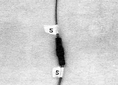
Figure 7.9. Before disconnecting the connector, attach tags to both sides.
It is also useful to make a sketch or photograph of the underhood space, indicating hoses, wiring, brackets, etc.
10. Disconnect the wiring harness connectors going to the engine from the junction box. Also disconnect the wiring harness connectors of the electronic control unit (ECM) in the passenger compartment (see chapter 6A or 6B) and pull the harness from the passenger compartment into the engine compartment.
11. Remove the generator and starter (see chapter 5) (see figure 7.11, a, b).
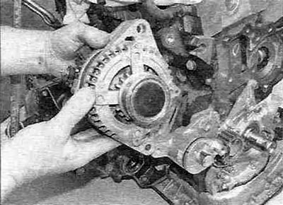
Figure 7.11,a. Removing the generator...
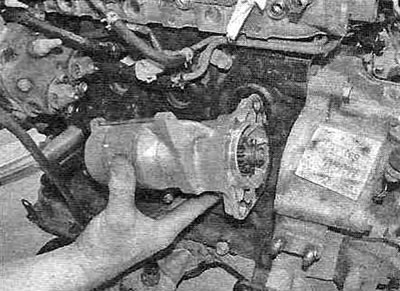
Figure 7.11, b....and the starter.
12. Remove the power steering pump (see chapter 10).
13. Remove the fan (fans) cooling, protective casing(s) and radiator (see chapter 3).
Note: This step is not mandatory, but is very helpful as it eliminates the possibility of damaging the radiator and fans when removing the engine from underneath. On automatic transmission models, if you are not removing the radiator, you will need to disconnect the oil cooler lines from the bottom of the radiator.
14. In models equipped with air conditioners, unscrew the air conditioner compressor mounting bolts and move it to the side without disconnecting the hoses. On these models, to provide additional space when removing the engine, it is recommended to remove the radiator so that the compressor can be moved further to the side. Also cover the air conditioner condenser with a piece of cardboard or plastic (see Figure 7.14).
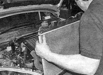
Figure 7.14. Removing the radiator.
15. Disconnect the exhaust pipe from the exhaust manifold (see chapter 4A or 4B).
16. Disconnect the gearbox drive, then disconnect the control cables from the front crossmember. Also disconnect all wiring harness connectors leading to the gearbox.
17. On models with manual transmission, disconnect the clutch release cylinder from the transmission (see chapter 8).
18. Remove the front drive shafts (see chapter 8). On four-wheel drive (4WD) models, drain the transfer case oil and remove the rear driveshaft (see Figure 7.18).
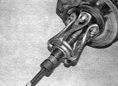
Figure 7.18. Using a puller to press the drive shaft out of the hub when removing the drive shaft.
19. On models produced since 2001, disconnect the stabilizer bar from the front cross member (see chapter 10). Also unscrew the two bolts securing the steering mechanism to the front crossmember and the bolts securing the lower ball joints to the lower suspension arms (see chapter 10). Tie the steering drive mechanism to the engine shield. It is preferable at this stage to remove the front crossmember by unscrewing the engine mounting bolts. Since it is quite heavy, use a trolley jack (see Figure 19, a-g).
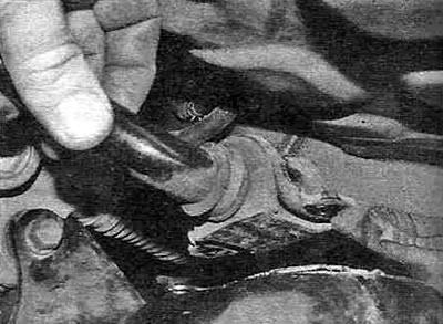
Figure 7.19,a. Disconnecting the anti-roll bar from the front crossmember.
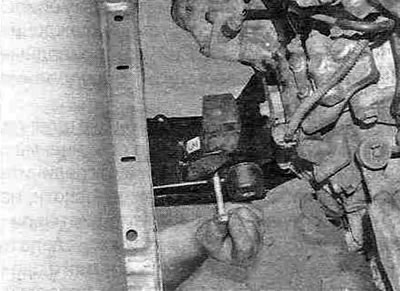
Figure 7.19, b. Loosen the mounting bolts...
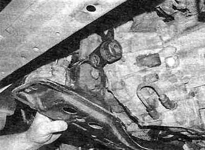
Figure 7.19, c....and remove the front crossmember from the engine.
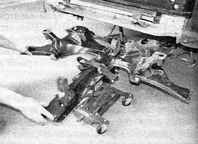
Figure 7.19, d. Removing the front crossmember from under the vehicle.
20. Attach the power unit to the sling strap or crane beam chain (see Figure 7.20).
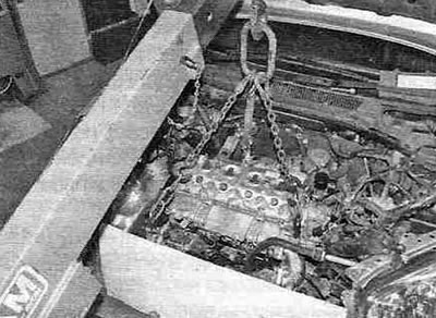
Figure 7.20. Securely hook the power unit and lift it until the chain is taut (sling tapes).
Fill the hoist and remove the jack from under the power unit. Remember that the automatic transmission will be outweighed when the unit is removed - it is heavier than the engine. Depending on the design of the hoist, it may be better to mount it on the side of the vehicle so that when the power unit is lowered, it is in the right place.
21. Check again that everything is disconnected (except for engine mounts), hang the missing tags.
22. Remove the through bolt from the left transmission mount and remove the engine mount from the passenger side.
23. If not already removed, remove the front cross member and unscrew the center cross member mounting bolts (see Figure 7.23).
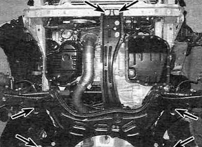
Figure 7.23. Location of front and center crossmember mounting bolts (a model with a gasoline engine is shown).
24. Gently lower the power unit.
Note: Place a piece of suitable plywood or old paneling on the floor under the power unit to make it easier to move.
25. After lowering the power unit to the floor, disconnect the hoist and lift the vehicle with a lift so that the power unit can be removed/pulled out.
Note: You will need an assistant to move the engine.
26. Reattach the power unit and raise it off the floor enough to allow the through bolts on the front and rear engine mounts to be removed, if necessary, and then the front crossmember to be pulled out from under the engine. Lower the engine to the floor and separate it from the gearbox (see chapter 7A or 7B). Make sure that the engine or gearbox does not tip over during this process - provide adequate supports using wooden wedges.
27. Remove the faceplate/flywheel and install the engine on the stand.
Installation
28. Check the condition of the engine/gearbox mounts and replace damaged or worn parts if necessary.
29. On models with manual transmission, check the condition of the clutch components (see chapter 8). In models with automatic transmission, check the condition of the torque converter seal and its bushing.
30. On manual transmission models, apply high temperature grease to the input shaft splines. On automatic transmission models, apply high temperature grease to the torque converter center hub.
31. Carefully install the gearbox into its place, following the procedure described in chapter 7A or 7B.
Warning. Do not attempt to achieve precise alignment of the engine and gearbox by tightening the mounting bolts - this can damage more than just the bolts.
32. Install the engine/transmission assembly mounting bolts and tighten them securely.
33. Move the engine/transmission assembly under the vehicle and position it in the desired position, first placing a piece of suitable plywood or old paneling on the floor, then lower the vehicle.
34. Attach the power unit to a sling or chain hoist in such a way that the balance is not disturbed during lifting, then slowly lift it to a height that allows you to secure the support on the gearbox side.
35. Support the transmission for safety with a floor jack, then install the front crossmember and right engine mount.
36. Install the remaining components in the reverse order of removal.
37. Fill with coolant, power steering fluid and automatic transmission fluid (if required) (see chapter 1A or 1B).
38. Start the engine and warm it up to normal operating temperature. Make sure there are no leaks and the engine is operating normally. Stop the engine and check the fluid levels.