
2. If the indicator lights up after more than 6 seconds, check the system for a malfunction.
3. Read fault codes (through the diagnostic connector).
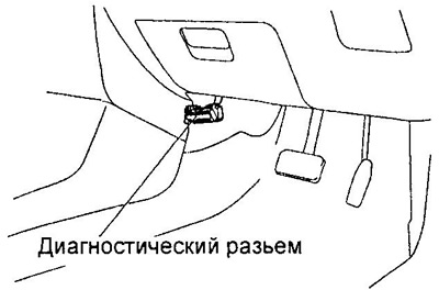
A) Turn the ignition switch to the ON position".
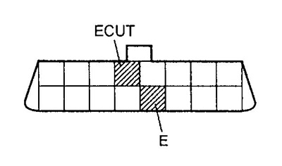
b) Connect the pins "ECUT" And "E" diagnostic socket.
Note: Wrong connection of pins can lead to failure of the system.
V) If there is no fault, the indicator lights up and goes out at 0.25 second intervals.
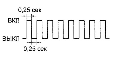
G) Fault code display.
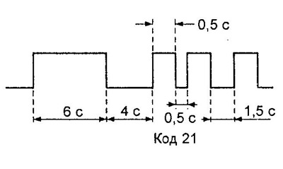
If there is a fault, the indicator flashes every 0.5 seconds. The first sequence of flashes corresponds to the first number of the diagnostic code, which consists of two numbers. After a pause of 1.5 seconds, a second sequence of flashes is displayed, corresponding to the second number of the code. If there are two or more fault codes, an interval of 2.5 seconds is set between them when outputting.
After all codes are displayed, there is a pause of 4 seconds, and then they all repeat while the diagnostic connector pins are closed.
The figure shows an example of the output of the code "21".
d) If the codes are not output, check the Tc output circuit of the diagnostic connector.
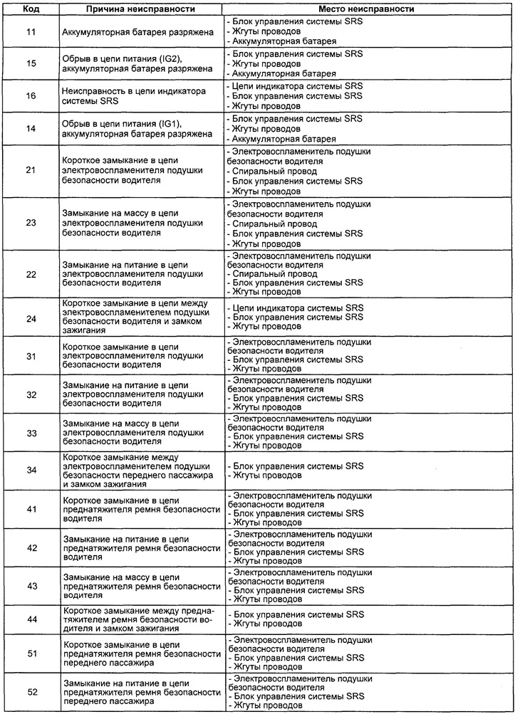
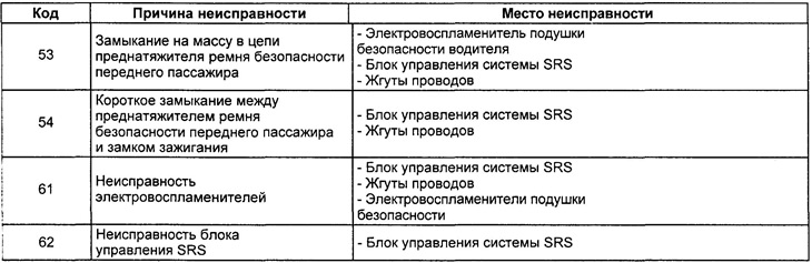
e) For an explanation of the fault codes, see the table "SRS System Fault Codes".
Erasing fault codes
Erasing diagnostic codes occurs when reconnecting the connectors "ECUT" And "E" diagnostic connector at intervals as shown in the figure.
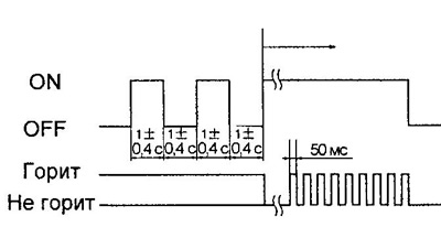
Table. Codes of malfunctions of system SRS.
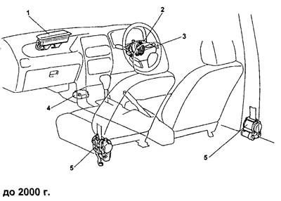
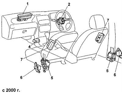
Layout of SRS elements.
1 - front passenger airbag,
2 - combined switch on the steering wheel,
3 - spiral wire,
4 - SRS electronic control unit,
5 - seat belt pretensioners,
6 - side airbag sensor,
7 - side airbag.
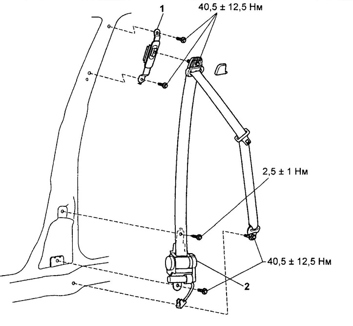
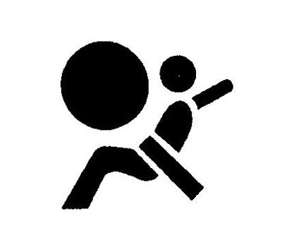
Seat belt pretensioner.
1 - seat belt mounting bracket,
2 - seat belt pretensioner.
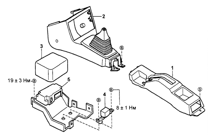
Electronic SRS control unit.
1 - rear of the center console,
2 - front part of the center console,
3 - cover of the SRS control unit,
4 - SRS sensor,
5 - SRS electronic control unit.