
Removal and installation
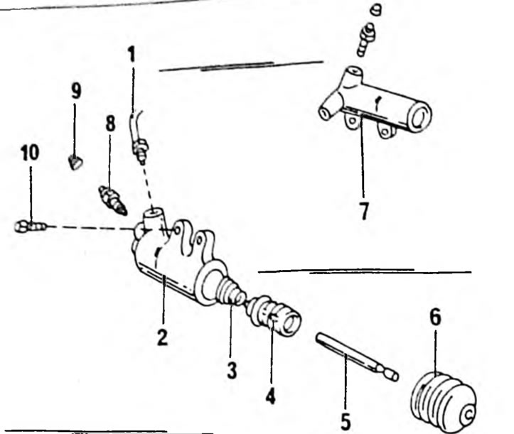
Pic. 166. Installation drawing of the clutch slave cylinder. The cylinder may look like (2) And How (1) 1. Clutch tube; 2. Cylinder (SSO gearbox); 3. Spring; 4. Piston; 5. Pusher rod; 6. Rubber cap; 7. Cylinder; 8. Air removal valve; 9. Anther; 10. Mounting bolt
Using Figure 166:
- Unscrew the union nut from the cylinder side and carefully pull out the tube. Close the end of the tube to prevent dirt from entering.
- Remove the cylinder bolts.
- Remove the cylinder.
- Install the cylinder in the reverse order. After installing the cylinder, remove air from the clutch hydraulic system (Chapter 8.7). No cylinder pusher adjustments are required.
Dismantling and assembling the clutch slave cylinder
Using Figure 166:
- Remove the dust cap from the cylinder (6) and remove the push rod (5).
- Pull out the piston (4) from the hole and remove the spring (3).
- Wash all parts in clean brake fluid. Install new cuffs and install all parts after immersion in brake fluid. Unscrew the air release valve (9) and check that it turns in and out easily. Air bleed screws must! It is easy to screw in and out, so the poppy is used to remove air.