



Removal
Remove the front wheel.
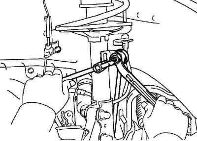
Fig. 4.23. Unscrewing the anti-roll bar strut mounting nut
Unscrew the anti-roll bar mounting nut (Fig. 4.23).
Caution: If the ball joint axle rotates with the nut, use a hex wrench (6mm) to hold the strut.
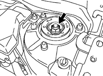
Fig. 4.24. Loosening the upper strut support lock nut
Loosen the lock nut of the upper strut support (Fig. 4.24).
Caution! Do not completely unscrew the nut.
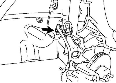
Figure 4.25. Disconnecting the brake hose and the speed sensor wiring harness (ABS)
Remove the brake hose bracket mounting bolt. Disconnect the brake hose, speed sensor wiring harness (ABS).
Disconnect the mounting clamps from the rack.
Remove 2 bolts and 2 nuts securing the shock absorber strut.
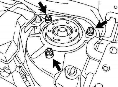
Fig. 4.26. Upper support strut mounting nuts
Unscrew the 3 nuts securing the upper support of the strut and remove the shock absorber strut (Fig. 4.26).
Install a bolt and two nuts on the bracket at the bottom of the rack and secure it in a vice.
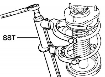
Fig. 4.27. Compressing the strut spring using a special tool
Using a special tool, compress the spring (Fig. 4.27).
Using the special tool, hold the upper spring cup and unscrew the nut.
Disassemble the strut by removing the upper strut mount, bearing, upper spring cup, shock absorber insulator, compression stop, spring and spring insulator.
Examination
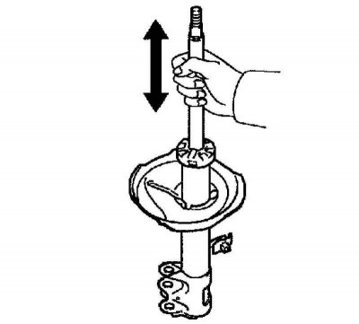
Fig. 4.28. Checking the shock absorber stroke
By pulling and pressing the shock absorber rod, check that its movement is smooth and there is no extraneous resistance or noise. If faulty, replace the shock absorber (Fig. 4.28).
Installation
Install the lower spring isolator onto the strut.
Install the spring compression stop on the piston rod.
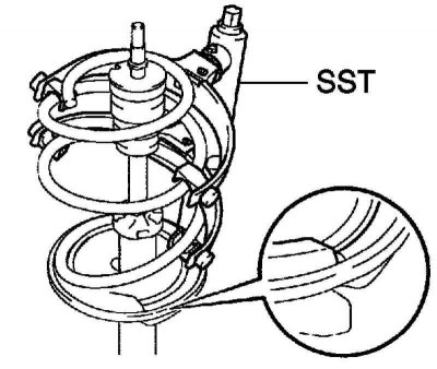
Fig. 4.29. Compressing the strut spring using a special tool
The original publication can be found on the website: toyotaman.ru
Using the special tool, compress the spring and install the spring on the strut (Fig. 4.29).
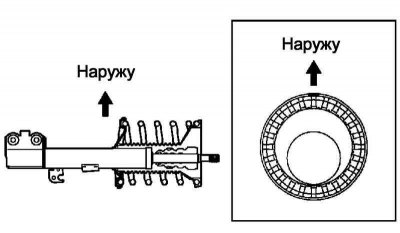
Fig. 4.30. Installation diagram of the shock absorber insulator and spring cup
Install the shock absorber insulator and spring cup. Align the "OUT" mark on the upper spring cup with the mark on the shock absorber insulator, as shown in Figure 4.30.
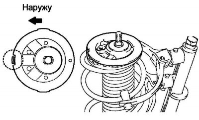
Fig. 4.31. Installing the spring cup in the correct position
Install the upper spring cup with the mark facing the rear of the vehicle (Fig. 4.31).
Install the bearing and upper strut mount, aligning them correctly with the rear of the vehicle.
Note: Make sure the bearing is seated in the upper strut mount.
Using the special tool, hold the upper spring seat and install the new nut.
Tightening torque: 47 Nm.
Install the remaining parts in the reverse order of removal.