
Measuring the height of certain points on the vehicle's chassis

Pic. 4.14. Measuring the height of certain points on the vehicle's chassis
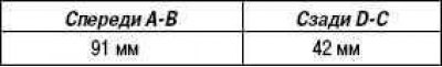
Height of some points of the vehicle chassis:
Except for N1 configuration
Equipment N1
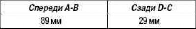
Measuring points:
- A: Distance from the center of the front wheel to the ground.
- B: Distance from the center of the front lower arm mounting bolt to the ground.
- C: distance from the center of the bridge beam bolt to the ground.
- D: distance from the center of the rear wheel to the ground.
Note. Before checking the front wheel alignment, adjust the height of the vehicle's chassis to the specified values.
Note. Rock the car at the corners of the body up and down to stabilize the suspension parts and check the height of the car's chassis.
Wheel alignment check
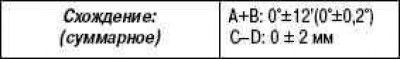
Note. the value «C-D» measure only if you measure «A+B» impossible.
Note. If the convergence does not correspond to the specified value, adjust the steering rods from the side of the steering rack.
Wheel alignment
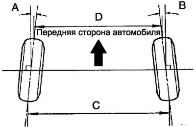
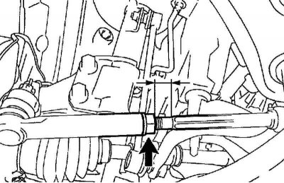
Pic. 4.15. wheel alignment
Measure the thread length of the left and right tie rods.
Nominal value: the difference in the length of the threaded part must not exceed 1.5 mm.
Remove clamps of fastening of covers of a slat.
Loosen the tie rod end nuts.
If the difference in the length of the threaded part of the right and left tie rods does not correspond to the nominal value, adjust the tie rods.
If the wheel alignment is outward, lengthen the shorter tie rod.
If the wheel alignment is inward, shorten the longer tie rod.
Adjust the toe by turning the right and left tie rod ends on the rack side by the same number of turns.
Note. It is recommended to adjust the convergence, focusing on the average value in the specified range.
Make sure the right and left tie rods are the same length.
Nominal deviation: 0±1 mm.
Tighten nuts of fastening of tips of steering draughts.
Tightening torque: 74 Nm.
Pic. 4.16. Tie rod adjusting nut
Note. Loosely tighten the locknut while holding the tie rod end on the hex so that it does not rotate with the nut. Hold the tie rod at the flattened area and tighten the lock nut (pic. 4.16).
Install the steering rack covers on the seats and secure with clamps.
Note. Make sure the covers are not twisted.
Calibrate the VSC stability control.
Checking the angles of rotation of the steered wheels
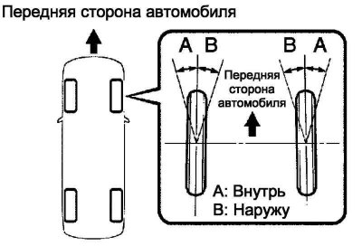
Pic. 4.17. Checking the angles of rotation of the steered wheels
Turn the steering wheel all the way to the left and right and measure the steering angles (pic. 4.17).
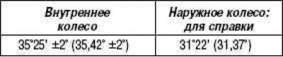
Wheel Angle:
Except for N1 configuration
Equipment N1
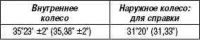
If the steering angles of the inner wheel (right or left) out of range, check the length of the right or left tie rods.
Checking the camber, longitudinal and transverse inclinations of the axis of rotation of the wheel
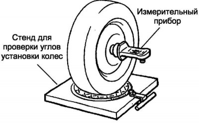
Pic. 4.18. Wheel alignment stand
Install the front wheels in the middle of the stand platforms to adjust the wheel alignment angles (pic. 4.18).
Remove the wheel cover.
Install a device for measuring camber, longitudinal and transverse inclination of the axis of rotation of the wheels, in the center of the wheel hub (drive shaft).
Check the camber, pitch and roll of the steering axis.
Camber, longitudinal and transverse inclination of the axis of rotation of the wheel:
Except for N1 configuration

Equipment N1

Note. Carry out the test with the vehicle unloaded (without spare wheel and tool kit).
Note. The maximum allowable difference in camber and caster between the left and right wheels is 45'.
Remove the device for measuring the camber, longitudinal and transverse angles of inclination of the axis of rotation of the wheels and the mount.
Install the wheel cover.
If the camber is adjusted correctly, and the longitudinal and transverse inclination of the axis of rotation of the wheel differ from the nominal values, check again that the suspension components and parts are not damaged or worn.
Camber adjustment
Remove the front wheel.
Note. After adjusting the camber, check the wheel alignment.
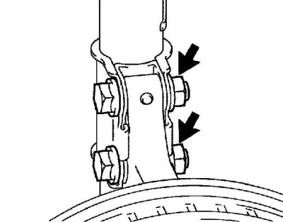
Pic. 4.19. Nuts on the underside of the front left shock absorber
Remove the 2 nuts from the underside of the front left shock absorber (pic. 4.19).
Clean the mating surfaces of the front left shock absorber assembly and steering knuckle.
Screw in 2 nuts.
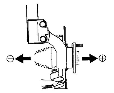
Pic. 4.20. Hub offset
Move the front wheel hub until it stops in the direction required for adjustment (pic. 4.20).
Tighten nuts.
Tightening torque: 220 Nm.
Install the front wheel.
Tightening torque: 103 Nm.
Check wheel alignment.
If the measured value differs from the nominal value, calculate the required adjustment value using the formula below.
(Camber adjustment amount) = average value of the nominal range - measured value.
Check the combination of installed bolts. To adjust the camber to the nominal range, select the appropriate bolts from the table below.

If the camber is not properly adjusted in accordance with the table above, body and suspension damage may result.
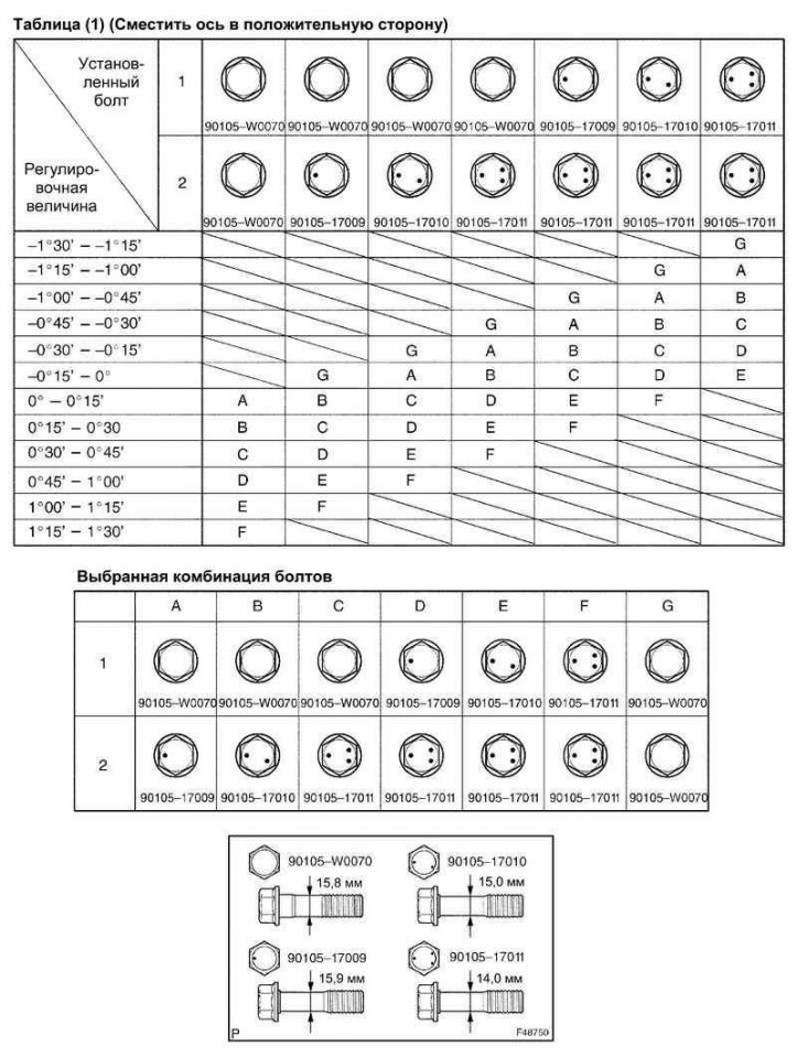
Pic. 4.21. Table No. 1 combinations of installed bolts
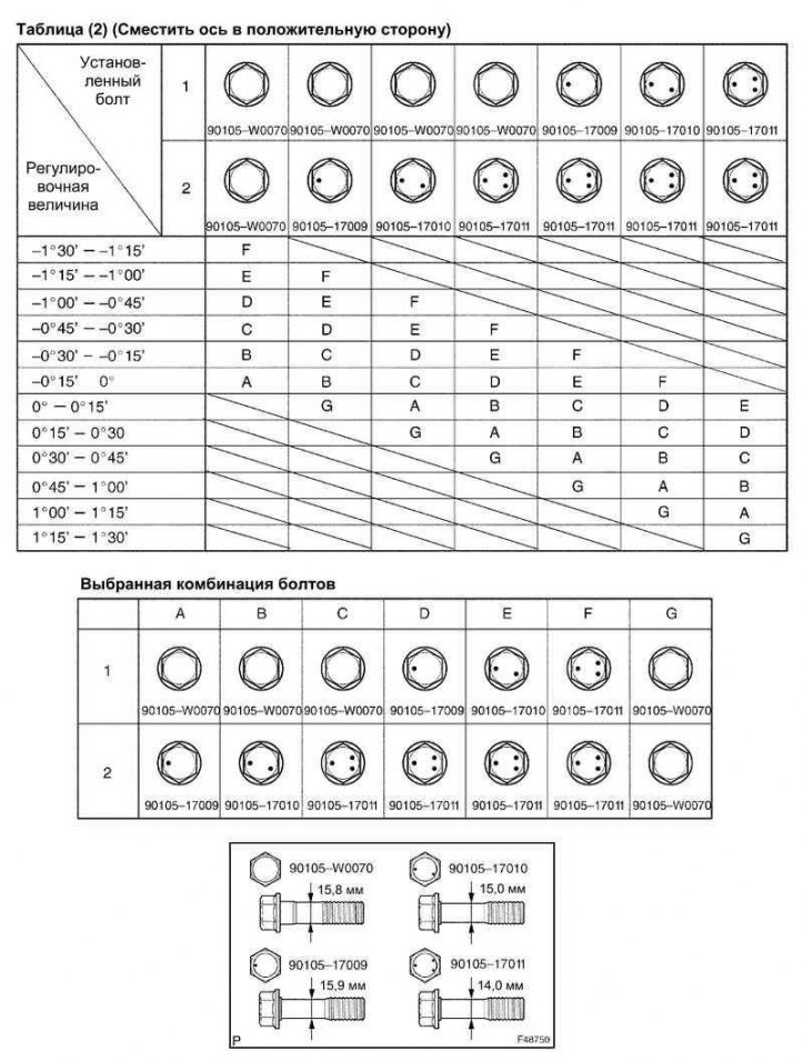
Pic. 4.22. Table No. 2 combinations of installed bolts
Note. When replacing a bolt, replace the nut with a new one. Repeat the above operations. Replace 1 or 2 selected bolts.
Note. When replacing 2 bolts, replace bolts one at a time.
If the camber is not properly adjusted in accordance with the table above, body and suspension damage may result.
Note. When replacing a bolt, replace the nut with a new one. Repeat the above operations. Replace 1 or 2 selected bolts.
Note. When replacing 2 bolts, replace bolts one at a time.