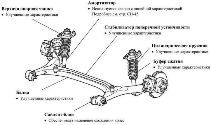
Pic. 4.6. Rear Suspension Components
Thanks to the optimal layout of the nodes, the optimization of the alignment in compression and rebound, the use of geometry that prevents the rear of the car from lifting when braking, an excellent ride and excellent handling of the car are achieved.
Rear wheel axle
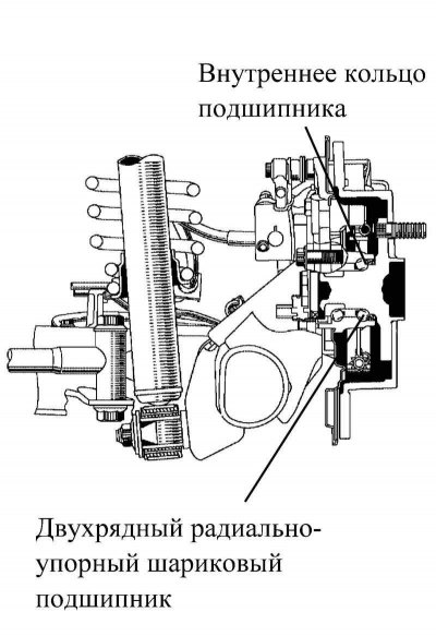
Pic. 4.7. Rear axle design
The rear wheel axle is mounted on a double-row angular contact ball bearing with low rolling resistance.
To increase the rigidity of the structure, the inner ring of the bearing is part of the axle trunnion.
Maintenance recommendation
When lifting the car, install the jack only under the places of the body specially provided for this purpose. It is forbidden to install a jack under the axle beam, trailing arm or silent block.
Changing the camber and wheel alignment
In a suspension with a torsion bar, the camber and toe angles change with the vertical movement of the wheel (hitting a hillock or depression), providing the car with straightness of movement and excellent cornering.
Hitting a hillock
Similarly to the independent suspension, the axis connecting the centers of the right and left silent blocks of the trailing arms is the center of rotation.
Hitting a depression
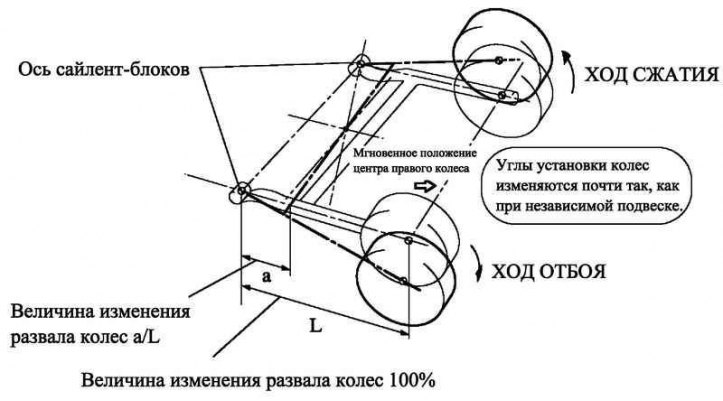
Pic. 4.8. Suspension axle compression and rebound travel
When hitting a depression or with a different amount of suspension travel of the right and left wheels, the torsion bar twists relative to the center of its section.
In addition, due to the difference in wheel suspension travel, the camber angle changes, the change is determined by the ratio of the distance between the axis of silent block 1 and the center of torsion twist (size «a» on the image) to the distance between the axle of the silent block 1 and the axle of the wheel (size «L» on the image). Therefore, by choosing the optimal distance from the silent block to the center of the wheel, the design provides an optimal camber angle depending on the suspension travel, which, in turn, provides the car with excellent directional stability when cornering.
Design that prevents the rear of the car from lifting when braking
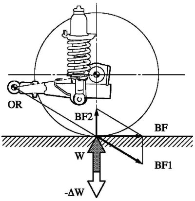
Pic. 4.9. The principle of operation of the design that prevents the rear of the car from lifting when braking
When braking, the force of inertia shifts the center of gravity forward, raising the rear of the car. The fulcrum OR takes the braking force BF and decomposes it into its components: BF1, the line of action of which passes through the fulcrum, and BF2, directed upwards.
Force BF1 tends to change the height of the fulcrum OR. When OR is raised, it acts in the direction (-?W), opposite to the alternating load (W), holding the car up.
Changing wheel alignment
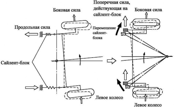
Pic. 4.10. The scheme of changing the toe of the wheels
Longitudinal and transverse forces acting on the car when cornering lead to deformation of the silent blocks of the suspension arms.
In a right turn, the right suspension arm moves forward and the left arm moves back, causing the left wheel to re-toe.
In this case, the design provides for the use of the energy of the lateral force acting during the turn on the silent blocks, which are the support of the trailing arms, to return the left suspension arm in the direction in which the toe becomes positive again. This achieves excellent ride and excellent handling of the car.
Table 4.3. Technical data for inspection and adjustment work
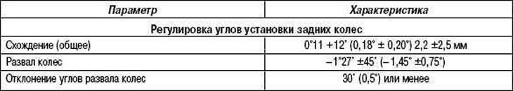
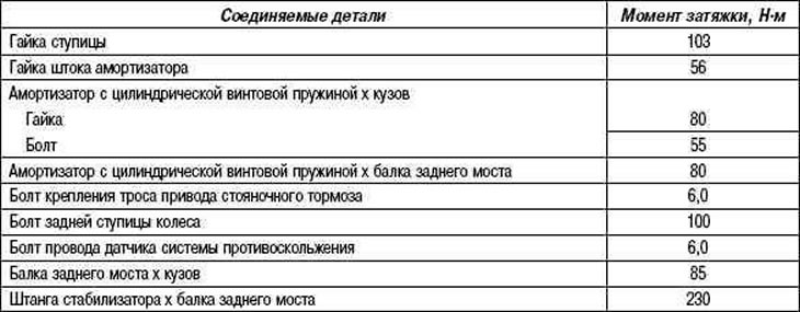
Table 4.4. Rated tightening torques