
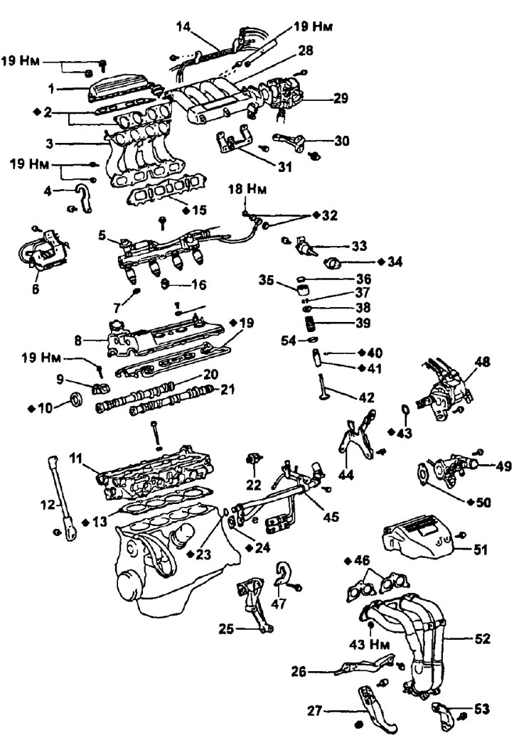
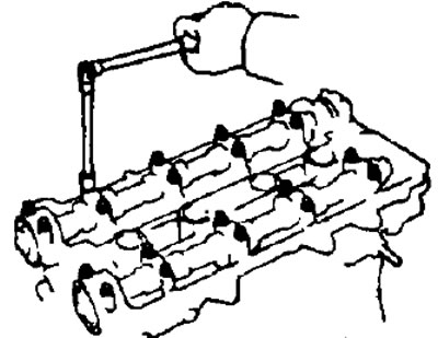
Removal and installation of a head of the block of cylinders: 1 - valve system with variable intake manifold geometry; 2 - gasket; 3 - intake manifold; 4 - right rear hook for lifting the engine; 5 - fuel manifold and injectors assy; 6 - node of the system with variable intake manifold geometry; 7 - insulator; 8 - cylinder head cover; 9 - camshaft bearing cap; 10 - camshaft seal; 11 - cylinder head; 12 - intake manifold bracket; 13 - cylinder head gasket; 14 - air tube; 15 - gasket; 16 - heat-insulating sleeve; 17 - sealing washer; 18 - gasket; 19 - gasket; 20 - intake camshaft; 21 - exhaust camshaft; 22 - oil pressure sensor; 23 - ring seal; 24 - gasket; 25 - bracket No. 1 of the generator; 26 - bracket No. 2 of the generator; 27 - exhaust manifold bracket; 28 - inlet chamber; 29 - throttle body; 30 - bracket No. 1 of the inlet chamber; 31 - bracket No. 2 of the inlet chamber; 32 - gasket; 33 - cold start nozzle; 34 - gasket; 35 - pusher; 36 - adjusting washer; 37 - crackers; 38 - valve spring plate; 39 - valve spring; 40 - retaining ring; 41 - valve guide; 42 - valve; 43 - ring seal; 44 - left hook for lifting the engine; 45 - coolant bypass pipe; 46 - gasket; 47 - right front hook for lifting the engine; 48 - distributor; 49 - coolant outlet pipe; 50 - gasket; 51 - exhaust manifold heat shield; 52 - exhaust manifold; 53 - exhaust manifold bracket; 54 - spring seat.
Removing the cylinder head
1. Disconnect the negative plug from the storage battery.
2. Drain the coolant from the cylinder block and radiator.
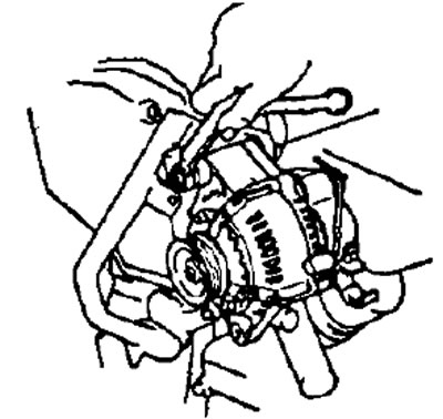
3. Remove the generator.
- A) Loosen the idler pulley bolt and adjusting bolt and remove the drive belt.
- b) Disconnect the generator connector.
- V) Remove the two bolts, disconnect the engine wiring harness from the brackets.
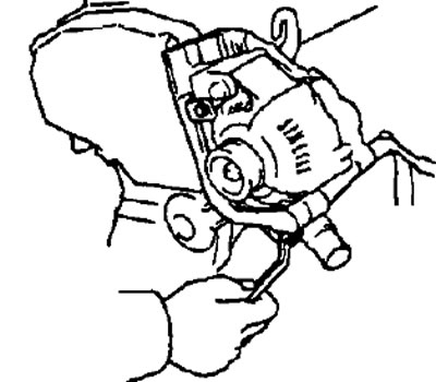
- G) Remove the two bolts and bracket #2 of the alternator.
- d) Turn away a nut and disconnect a wire of the generator.
- e) Turn away two bolts and the generator.
4. Remove the right front engine lifting hook and alternator bracket #1 by removing the three bolts.
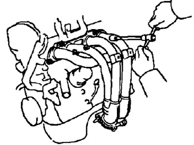
5. Remove the exhaust manifold.
- A) Disconnect the intake pipe.
- b) Remove the five bolts and remove the exhaust manifold heat shield.
- V) Turn away three bolts, a nut and remove the right arm of a collector.
- G) Remove the two bolts and remove the left manifold bracket.
- d) Remove six nuts, exhaust manifold and two gaskets.
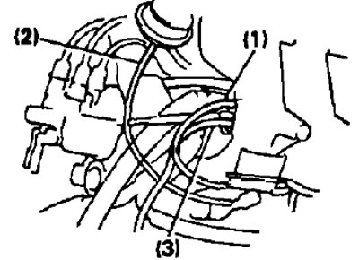
6. Remove the coolant outlet fitting.
- A) Disconnect the following connectors:
- coolant temperature sensor connector,
- coolant temperature sensor.
- cold start injector timer connector.
- b) Disconnect the following hoses:
- (1) upper radiator hose
- (2) coolant bypass hose from the bypass tube,
- (3) coolant bypass hose from the idle control valve,
- (4) heater hose.

- V) Unscrew the two bolts, remove the coolant outlet pipe and the gasket.
7. Remove the oil pressure sensor.
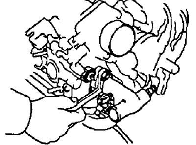
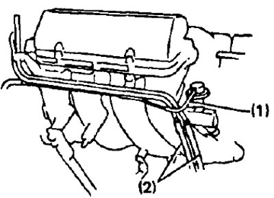
8. Remove the coolant bypass pipe.
- A) Disconnect the following hoses:
- (1) coolant bypass hose from the idle control valve,
- (2) coolant bypass hose from the cylinder block,
- (3) two coolant bypass hoses from the oil cooler,
- (4) heater hose.
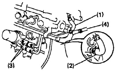
- b) Remove two bolts and two nuts, remove the coolant bypass tube, gasket and O-ring.
9. Remove the throttle body.
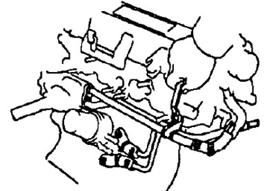
10. Remove the air tube.
- A) Disconnect the following hoses:
Note: Mark all hoses with paint prior to removal for proper installation.
- (1) vacuum hose from the fuel pressure regulator,
- (2) two vacuum hoses for the power steering pump,
- (3) two vacuum hoses from the intake chamber,
- (4) vacuum hose from a vacuum tube (from the electro-pneumatic valve of the fuel pressure regulator).
- b) unscrew the two bolts and remove the air tube.
11. Remove the intake manifold bracket by removing the two bolts.
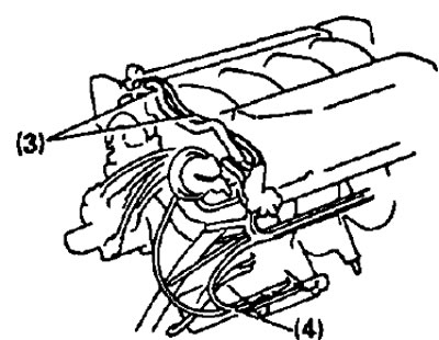
12. Remove the intake manifold geometry change system assembly.
- A) Disconnect the following connectors:
- connector for the solenoid valve of the fuel pressure regulator;
- solenoid valve connector.
- b) Disconnect the following hoses:
- (1) vacuum hose (from the electro-pneumatic valve of the fuel pressure regulator) from the intake manifold
- (2) vacuum hose (from electropneumatic valve) from the drive
- (3) vacuum hose (from the vacuum tank) from the intake manifold
- V) Turn away three bolts, remove knot of system of change of geometry of an inlet manifold.
13. Remove the cold start injector.
14. Remove the inlet chamber.
- A) Remove four bolts and remove bracket #2.
- b) Turn away six bolts and two nuts, remove an inlet chamber and a lining.
- V) Remove two bolts and remove bracket #1.
15. Remove the distributor.
16. Remove the left engine lifting hook by removing the two bolts.
17. Remove the intake manifold variable geometry valve by unscrewing the two bolts and two nuts and remove the gasket.
18. Remove the intake manifold.
- A) Loosen the bolt and disconnect the wire "grounding".
- b) Disconnect the knock sensor connector.
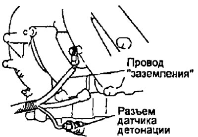
- V) Remove four bolts, three nuts, intake manifold and gasket.
19. Remove the right rear engine lifting hook by removing the bolt.
20 Disconnect the engine wiring harness from the cylinder head cover.
- A) Disconnect the four injector connectors.
- b) Remove the two bolts and disconnect the engine wiring harness from the cylinder head cover.
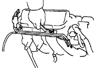
21. Remove the fuel manifold and injectors.
Note: do not lose the heat-insulating sleeves and insulators.
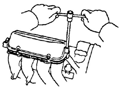
22. Remove the cylinder head cover. Remove ten screws, washers, cylinder head cover and two gaskets.
23. Remove the camshaft pulleys. (see section "timing belt (3S-GE engine) points 6-9).
24. Remove the tension roller. (see paragraph 14).
25. Remove the timing belt cover No. by unscrewing the five bolts.
Note:
- Support the timing belt so that the engagement of the crankshaft sprocket and timing belt does not change.
- Be careful not to drop foreign objects inside the timing belt cover
- Keep oil, water or dust away from the timing belt.
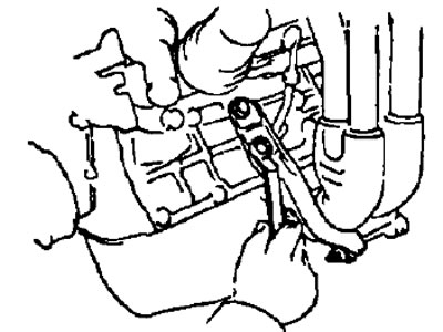
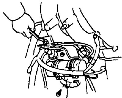
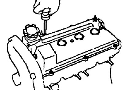
26. Evenly loosen and remove the ten bearing cap bolts in several passes. Remove the camshaft bearing caps, oil seals, and then the camshafts themselves.
Note: Pre-measure the clearances in the valve drive in order to facilitate adjustment after assembly.
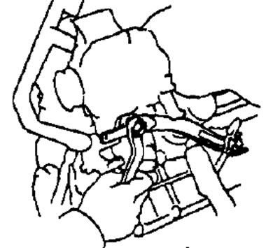
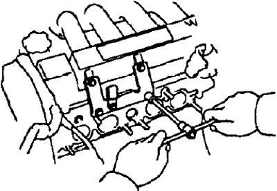
27. Remove the cylinder head.
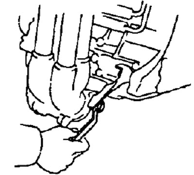
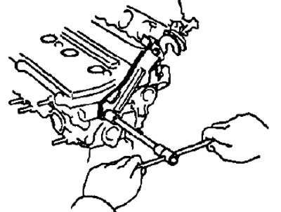
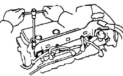
- A) Evenly loosen and remove the ten cylinder head bolts in several passes in the sequence shown in the figure
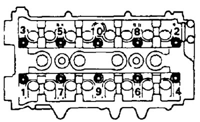
Note: Incorrect bolt loosening may result in cylinder head deformation or cracking.
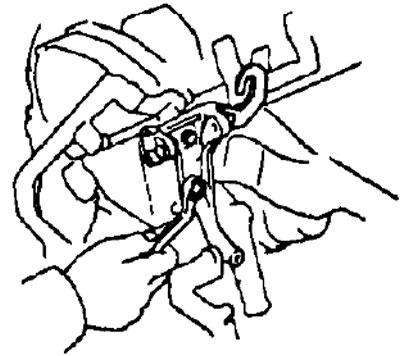
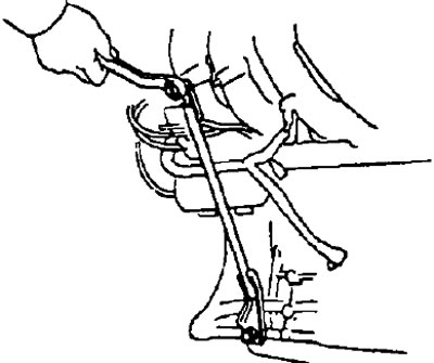
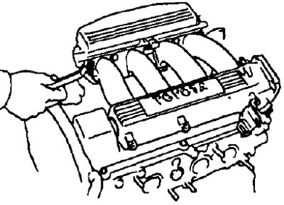
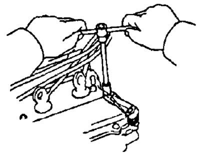
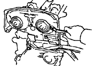
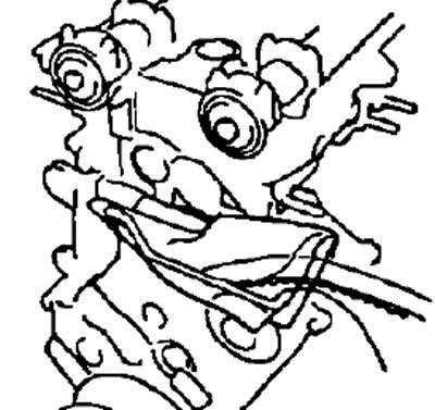
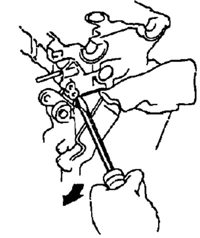
- 6) Remove the cylinder head from the guide pins on the cylinder block and lay it on a workbench with a piece of wood and a rag underneath.
Note: If the block head is difficult to remove, you can use a powerful screwdriver, inserting it into the gas joint, as shown in the figure. However, take care not to damage the surfaces of the head and block, as well as the head gasket.
Checking the system for changing the geometry of the intake manifold
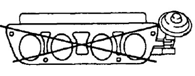
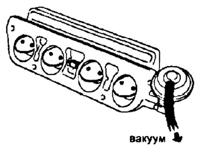
1. Check the intake manifold control valve.
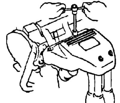
- A) With a precision ruler and a flat feeler gauge, check the intake manifold surface for flatness.
- Maximum flatness - 0.20 mm
- b) Apply a pressure of 53.3 kPa to the valve and check that the valve slowly moves to the closed position.
- V) Check that the valve opens quickly under vacuum.
2. Check the vacuum tank.
- A) Check that the air entering the port "A" leaves in one direction from the port "IN" and does not leave the port "A" when air is supplied to the port "IN".

- b) Apply a vacuum of 66.7 kPa to the port "A" and check that there is no pressure change after one minute.