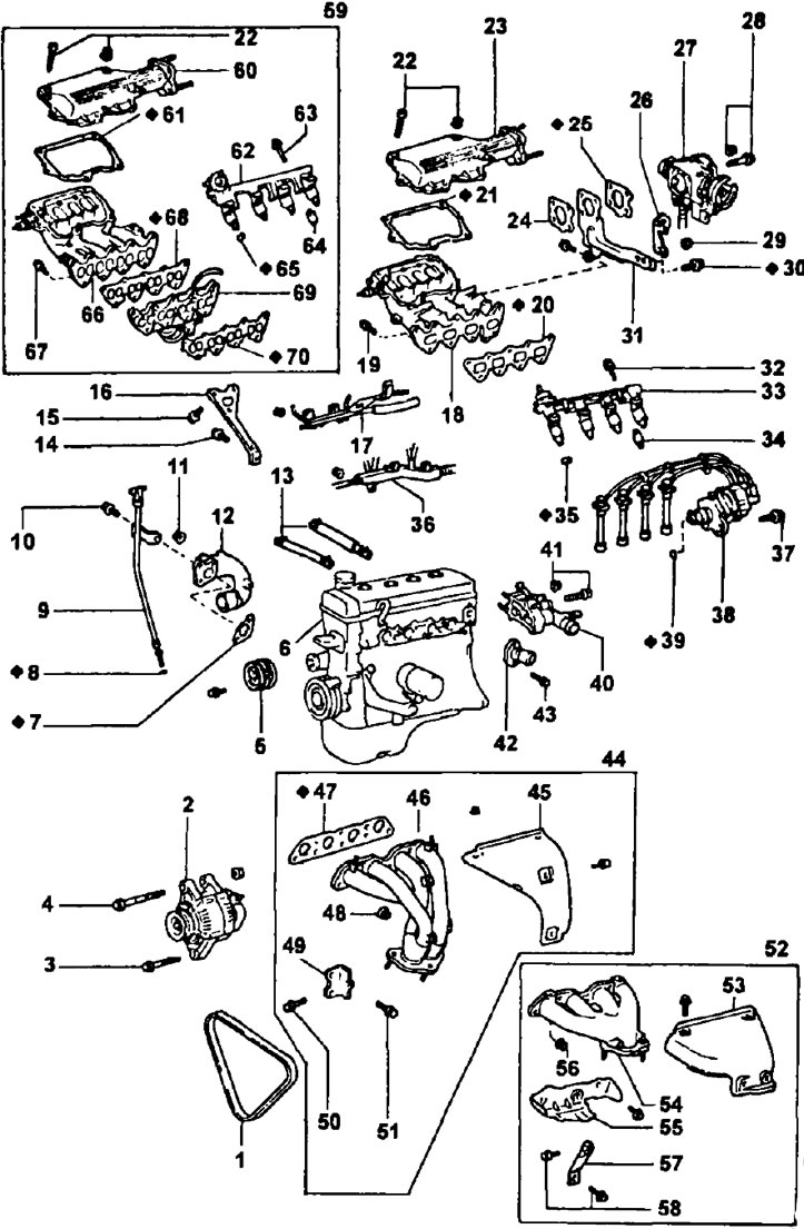
Removing the cylinder head. 1 - drive belt for the generator and coolant pump; 2 - generator; 3 - alternator lock bolt (М3=18 Nm); 4 - alternator mounting bolt (М3=58 Nm); 5 - coolant pump drive pulley; 6 - cylinder block with a block head in the assembly; 7 - gasket for the inlet pipe No. 2 of the coolant; 8 - sealing ring of the oil dipstick; 9 - oil dipstick assembly with guide; 10 - fixing bolt of the inlet pipe No. 2 of the coolant (M3=9.3 Nm); 11 - nut for fastening the inlet pipe No. 2 of the coolant (M3=15 Nm); 12 - inlet pipe No. 2 of the coolant; 13 - hoses of the forced crankcase ventilation system; 14 - a bolt of fastening of a support rack of an inlet collector (М3=39 Nm); 115 - intake manifold mounting bolt (М3=19 Nm); 16 - support rack of the intake manifold; 17 - air bypass tube; 18 - intake manifold; 19 - intake manifold mounting bolt (М3=19 Nm); 20 - intake manifold gasket; 21 - gasket cover of the air intake chamber; 22 - bolt for fastening the cover of the air intake chamber; 23 - air intake chamber cover; 24 - gasket between the flange of the inlet pipe of the air inlet chamber and the support post of the air inlet chamber; 25 - gasket under the throttle body; 26 - transport hook (eye) engine; 27 - throttle body; 28 - throttle body mounting bolt (М3=22 Nm); 29 - eye nut (М3=28 Nm); 30 - a bolt of fastening of a support rack of the chamber of an inlet of air (М3=28 Nm); 31 - support post of the air intake chamber; 32 - fuel manifold mounting bolt (M3=15 Nm); 33 - fuel manifold assembly with injectors; 34 - heat-insulating sleeve of the nozzle collector; 35 - nozzle insulator; 36 - engine wiring; 37 - a bolt of fastening of the integrated block of ignition (block contactless ignition system) M3=20 Nm; 38 - combined ignition unit (ignition distributor with ignition coil or contactless ignition system unit) with high voltage wires; 39 - sealing ring of the housing of the sensor-distributor of ignition; 40 - coolant inlet pipe and coolant supply unit to the cylinder head; 41 - bolt for fastening the coolant supply unit to the cylinder head (M3=20 Nm); 42 - branch pipe for draining coolant from the cylinder head; 43 - bolt for fastening the coolant outlet pipe (M3=15 Nm); 44 - details of the exhaust manifold for production engines with a catalytic converter of exhaust gases; 45 - exhaust manifold heat shield; 46 - exhaust manifold; 47 - exhaust manifold gasket; 48 - exhaust manifold mounting nut (М3=34 Nm); 49 - exhaust manifold support bracket; 50 - exhaust manifold support bracket bolt (М3=39 Nm); 51 - exhaust manifold support bracket bolt (М3=59 Nm); 52 - details of the exhaust manifold for other engines; 53 - upper heat-insulating casing of the exhaust manifold; 54 - exhaust manifold; 55 - lower heat-insulating casing of the exhaust manifold; 56 - exhaust manifold mounting nut (М3=34 Nm); 57 - exhaust manifold support; 58 - exhaust manifold mounting bolts (М3=39 Nm); 59 - details of the air intake chamber and intake manifold for an engine with a lean mixture combustion system; 60 - air intake chamber cover; 61 - gasket cover of the air intake chamber; 62 - fuel manifold assembly with injectors; 63 - a bolt of fastening of the general fuel line (collector) nozzles (M3=9.3 Nm); 64 - remote bushing (spacer) nozzle bolt; 65 - nozzle insulator; 66 - intake manifold; 67 - intake manifold mounting bolt (М3=19 Nm); 68 - intake manifold gasket; 69 - spacer (frame) additional shutters; 70 - gasket for the body of additional controlled dampers.
Note: In this engine, the intake manifold has 8 separate intake pipes connecting the air intake chamber (resonator) with each inlet valve, in the channels of the spacer directly in front of the inlet valves, additional dampers controlled by a servo mechanism are installed, partially blocking the channels at low loads.
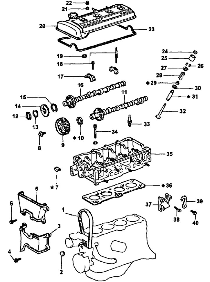
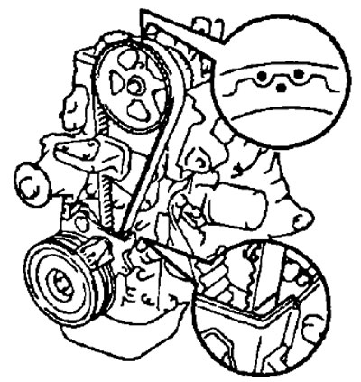
Removing the cylinder head (continuation).
1 - timing belt; 2 - rubber stopper; 3 - cover No. 2 of the timing belt; 4 - bolt for fastening the cover No. 2 of the timing belt (M3=7.4 Nm); 5 - cover No. 3 of the timing belt; 6 - bolt for fastening the cover No. 3 of the timing belt (M3=7.4 Nm); 7 - segment plug (part; installed with a pre-primer); 8 - a bolt of fastening of a pulley of a drive of a camshaft of final valves (М3=59 Nm); 9 - exhaust camshaft drive pulley; 10 - stuffing box; 11 - exhaust camshaft; 12 - lock (crimp) ring; 13 - wavy spring washer; 14 - auxiliary gear of the intake camshaft; 15 - leaf spring of the gear of the camshaft of the intake valves; 16 - intake camshaft; 17 - camshaft bearing cover; 18 - a bolt of fastening of a cover of the bearing of a camshaft (M3=13 Nm); 19 - gasket for the protective tube of the spark plug; 20 - timing cover (cylinder heads); 21 - sealing washer; 22 - cap nut; 23 - cylinder head cover gasket; 24 - adjusting washer (for adjusting the thermal clearance in valves); 25 - valve pusher; 26 - crackers; 27 - plate (holder) valve springs; 28 - valve spring; 29 - valve oil cap; 30 - support washer (saddle) valve springs; 31 - valve guide; 32 - valve; 33 - spark plug; 34 - a bolt of fastening of a head of the block of cylinders (М3=29 Nm); then sequentially tighten each bolt by 90°; then tighten each bolt again by 90°; 35 - cylinder head; 36 - cylinder head gasket; 37 - generator mounting bracket; 38 - alternator bracket bolt (M3=26 Nm); 39 - transport hook (eye) engine; 40 - eye bolt (М3=28 Nm).
Removing the cylinder head
1. Disconnect the wire from the negative battery terminal.
2. Drain the coolant.
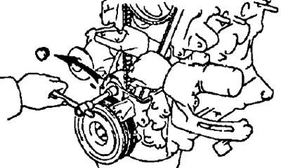
3. Remove the alternator and coolant pump drive belt (see subsection "Removing the timing belt" section "timing belt").
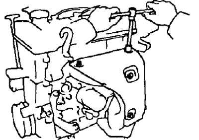
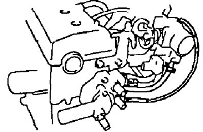
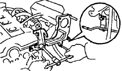
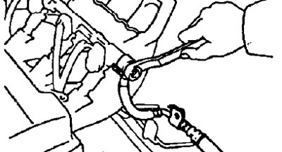
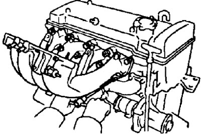
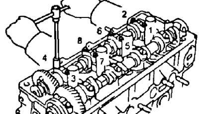
4 Disconnect the engine wiring by first disconnecting or removing: alternator connector (1), generator wiring (2), emergency oil pressure sensor connector (3), two cable ties (4).
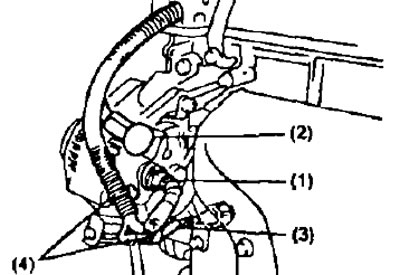
Then remove the engine wiring protection and disconnect the wiring from the cylinder head.
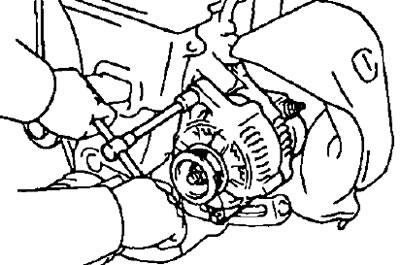
5. Remove the generator by unscrewing its fastening bolt, nut and adjusting bolt.
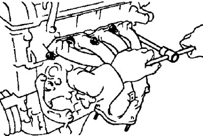
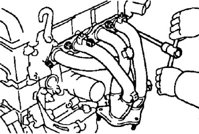
6. Remove the exhaust manifold.
4A-FE (serial version)
- A) Turn away 3 bolts, 2 nuts and remove the top heat-shielding casing.
- b) Remove the 3 bolts and remove the exhaust manifold support.
- V) After unscrewing 5 nuts, remove the exhaust manifold and gasket.
4A-FE (except for the serial version)
- A) Remove 4 bolts and remove the top heat shield.
- b) Remove the 2 bolts and remove the exhaust manifold support.
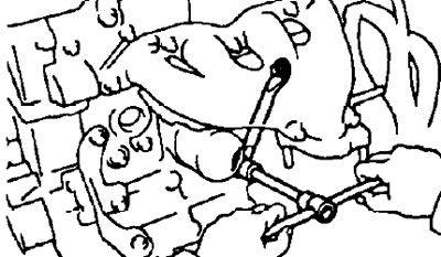
- V) After unscrewing 5 nuts, remove the exhaust manifold and gasket.
- G) Remove the 3 bolts and remove the lower heat shield from the exhaust manifold.
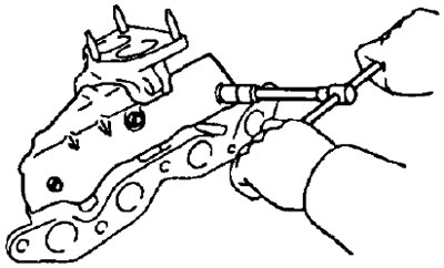
(7A-FE)
- A) Remove 4 bolts and remove the top heat shield.
- b) Loosen the strut-to-exhaust manifold bolt.
- V) After unscrewing 5 nuts, remove the exhaust manifold and gasket.
- G) Remove the 2 bolts and remove the exhaust manifold support.
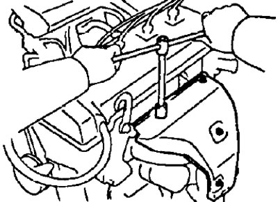
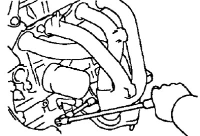
7. Remove the coolant outlet pipe by unscrewing the two mounting bolts.
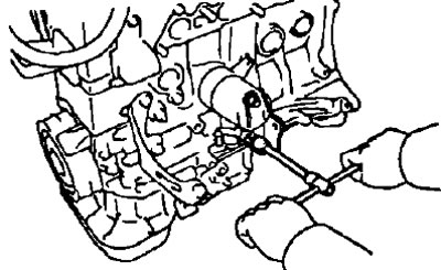
8. Remove the combined ignition unit (ignition distributor with ignition coil (block contactless ignition system), having previously removed the high-voltage wires (holding them only by the rubber covers) and unscrewing the 2 nuts securing the combined ignition unit.
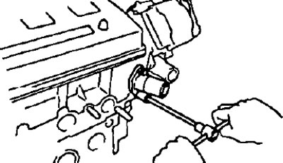
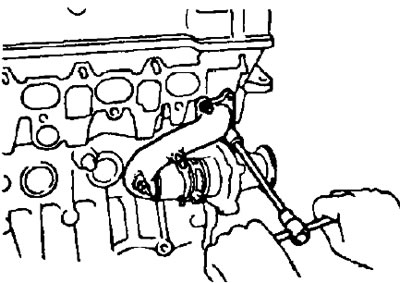
9. Remove the case of branch pipes of a supply of a cooling liquid to a head of the block of cylinders.
- A) Disconnect the coolant temperature sensor connector, the coolant bypass hoses and the vacuum hose of the bimetal electro-pneumatic valve of the evaporative emission system.
- b) Turn away a bolt and 2 nuts and remove the case of branch pipes of a supply of a cooling liquid.
10. Remove the throttle body (see chapter "fuel injection system (gasoline engines) ").
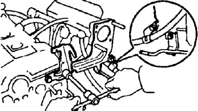
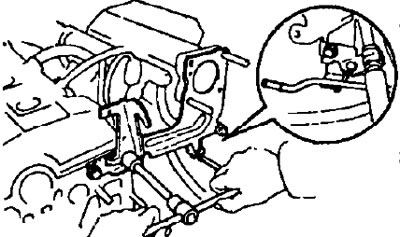
11. Remove the transport hook (eye) engine, having previously unscrewed the bolt (or bolts) and disconnecting the air bypass pipe and the fuel supply pipe. Then, having unscrewed the bolt and nut, remove the eye, the support post of the air intake chamber (resonator) and padding.
7A-FE.
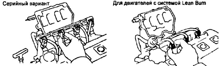
4A-FE (serial version).
4A-FE (version with Lean Bum system).
12. Remove the intake manifold support by removing the 3 bolts.

13. Remove the air bypass pipe by first disconnecting the fuel return line pipe and unscrewing the bolt and nut.

14. Disconnect the engine wiring from the intake manifold by removing the bolt and 2 nuts.
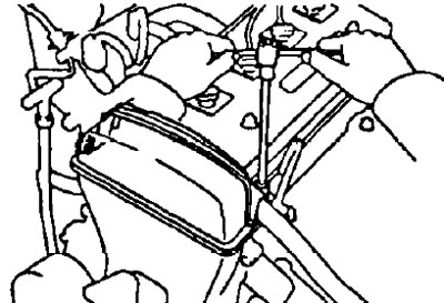
15. Remove the air intake chamber cover:
Disconnect 2 system hoses: forced crankcase ventilation and vacuum transmission hose.
Using a 6mm Allen wrench, remove the 3 bolts, 2 nuts, and remove the air intake chamber cover and gasket.
16. Disconnect the fuel return line tube from the fuel differential pressure regulator.
17. Disconnect the fuel supply pipe from the common fuel line (collector) injectors by unscrewing and removing the bypass bolt with gaskets.
18. Disconnect the injector connectors.
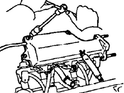
19. Remove the fuel manifold assembly with injectors.
- A) Remove 2 bolts (for engines with Lean Bum system - 3 bolts) and remove the injector manifold with injectors.
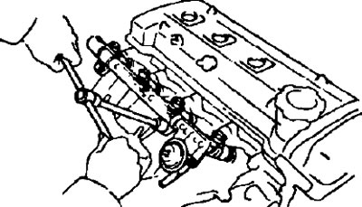
4A-FE (serial version) and 7A-FE.
4A-FE variant with Lean Bum system.
Note: Do not drop the injectors while removing the manifold.
- b) Remove 4 insulators and 2 spacers (for engines with Lean Burn system - 3 spacers) from the intake manifold.
- V) Remove 4 injectors from common fuel line (collector) nozzles.
- G) Remove the O-ring and rubber bushing from each injector.
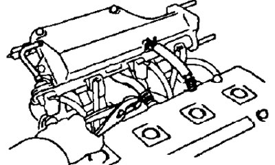
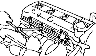
20. Remove 7 bolts, 2 nuts and intake manifold with gasket (for engines with Lean Bum system - with two gaskets and an air bypass valve).
21. Remove the oil level indicator from the guide, unscrew the mounting bolt, remove the entire assembly (guide pointer) and remove the O-ring.
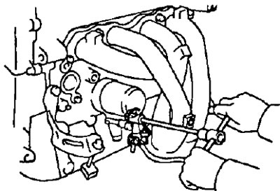
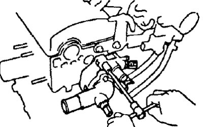
22. Remove branch pipe No. 2 of a supply of a cooling liquid.
- A) Loosen the 2 nuts securing the nozzle to the head.
- b) Disconnect the inlet pipe from the coolant pump.
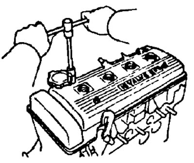
23. Remove the spark plugs using a special wrench
24. Remove the cylinder head cover with gasket by unscrewing the 4 cap nuts and removing the seals.
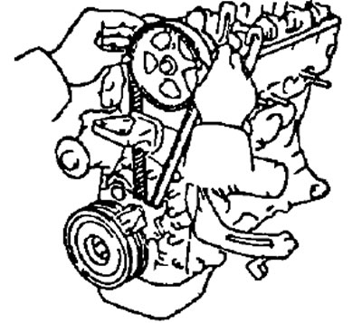
25. Remove protective casings No. 3 and No. 2 of the timing belt.
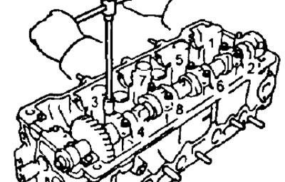
26. Set the piston of the 1st cylinder to TDC at the end of the compression stroke.
- A) Rotate the crankshaft pulley and align the groove on the pulley with the timing mark "ABOUT" on the protective cover No. 1 of the timing belt.
- b) Make sure the small hole in the exhaust camshaft drive sprocket aligns with the alignment mark on the 1st camshaft bearing cap.
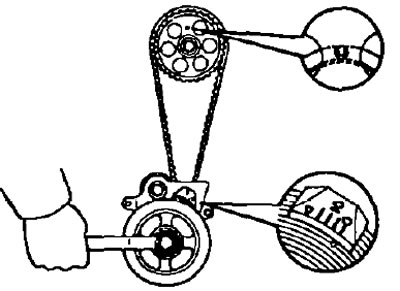
Otherwise turn the crankshaft one more turn (360").
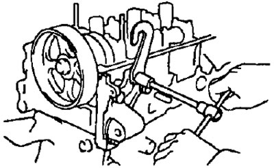
27. Remove the timing belt from the camshaft sprocket.
- A) Put alignment marks on the toothed pulley and on the timing belt, as well as a mounting mark on the belt at the point of its exit from the protective cover No. 1 of the timing belt.
- b) Remove the rubber stopper from the #1 timing belt cover.
- V) Loosen the timing belt tensioner bolt, move the idler to the left as far as it will go, and temporarily re-tighten the idler bolt.
- G) Remove the toothed belt from the camshaft drive gear pulley.
Notes:
- Hold the belt in such a way as to prevent the belt from changing its engagement with the crankshaft sprocket.
- Do not allow any objects to fall into the timing belt guard.
- Keep the belt away from oil, water or dirt.
28. Remove the transport hook (eye) engine and alternator mounting bracket.
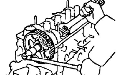
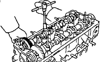
29. Remove the timing belt pulley from the camshaft, having previously fixed the camshaft with an adjustable wrench and unscrewing the pulley bolt.
30. Remove the intake and exhaust camshafts. Note: Since the camshaft end play is very small, to prevent jamming and/or damage to the camshaft when removing it, it is necessary to keep the shaft in a horizontal position, for this it is necessary to follow the dismantling procedure below
- A. Remove the intake camshaft.
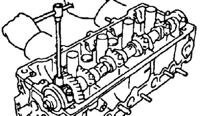
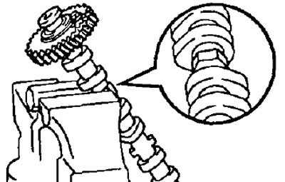
- A) Rotate the intake camshaft so that the sub gear locating hole is in the position shown in the figure.
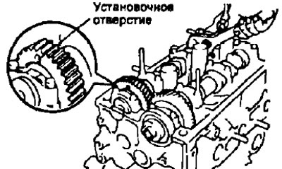
In this case, the cams of the intake camshaft evenly press on the valve lifters of the 1st and 3rd cylinders.
- b) Turn away 2 bolts and remove a cover of the 1st bearing of a camshaft.
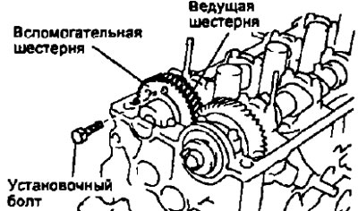
- V) Install the intake camshaft sub gear with the drive gear with the set bolt.
- The recommended mounting bolt is M6x1, 16-20 mm long.
Note: When removing the camshaft, make sure that this operation neutralizes the torsional force of the auxiliary gear torsion spring.
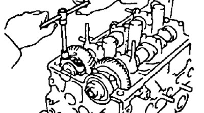
- G) Loosen the intake camshaft bearing cap bolts evenly in several passes in the sequence shown in the figure and remove the bolts.
- d) Remove the intake camshaft bearing caps and then the camshaft itself.
Note:
- Do not apply much force or try to use a screwdriver or any other object as a lever
- If the camshaft cannot be removed, install the 3rd bearing cap, tighten it, and then loosen the bolts while pulling the shaft by the gear.
- B. Remove the exhaust camshaft.
- A) Turn the exhaust camshaft with an adjustable wrench until the dowel pin is in the position shown in the figure.
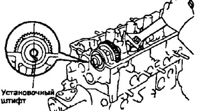
In this case, the cams of the exhaust camshaft evenly press on the valve lifters of the 1st and 3rd cylinders.
- b) Turn away 2 bolts and remove a cover of the 1st bearing of a camshaft.
- V) Loosen the exhaust camshaft bearing cap bolts evenly in several passes in the sequence shown in the figure and remove the bolts.
- G) Remove the exhaust camshaft bearing caps and then the camshaft itself.
Note:
- Do not apply much force or try to use a screwdriver or any other object as a lever.
- If the camshaft cannot be removed, install the 3rd bearing cap, tighten it, and then loosen the bolts while pulling the shaft by the gear.
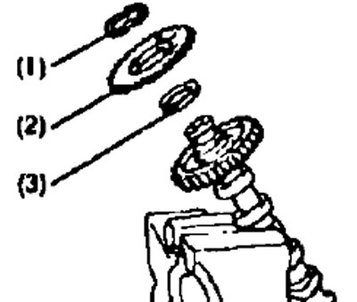
31. Disassemble the intake camshaft.
- A) Clamp the camshaft with its hexagonal part in a vise.
Note: Be careful not to damage the camshaft.
- b) Enter technological bolts (A) And (IN) into the technological holes of the auxiliary gear of the camshaft.
- V) Using a screwdriver, turn the camshaft sub gear clockwise and hit the access bolt (WITH).
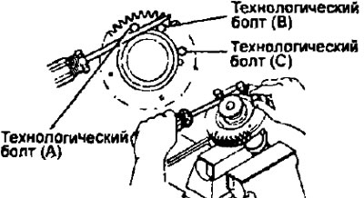
Attention: do not damage the camshaft.
- G) Remove the retaining ring with pliers.
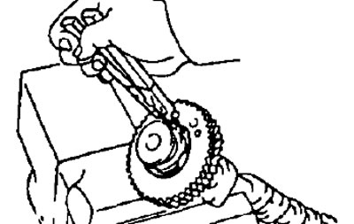
- d) Remove: spring washer (1), auxiliary camshaft gear (2) and gear spring (3).
32. Remove the segment (semicircular) plug
33. Remove the cylinder head.
- A) Using a suitable tool, loosen and remove the cylinder head bolts evenly over several passes in the sequence shown in the figure, and then remove 10 washers.
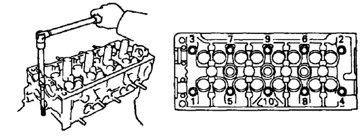
Attention: warping or cracking of the head of the block may be the result of a violation of the sequence of loosening the bolts of the block head.
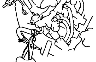
- b) Lift the cylinder head off the dowel pins and place it on a workbench with wood blocks underneath.
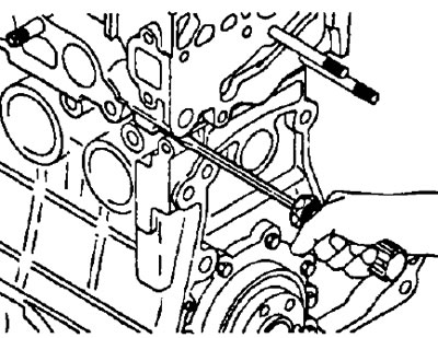
Attention: if the block head is difficult to remove, you can use a screwdriver, inserting it into the gas joint, as shown in the figure. However, take care not to damage the surfaces of the head and block, as well as the head gasket.