
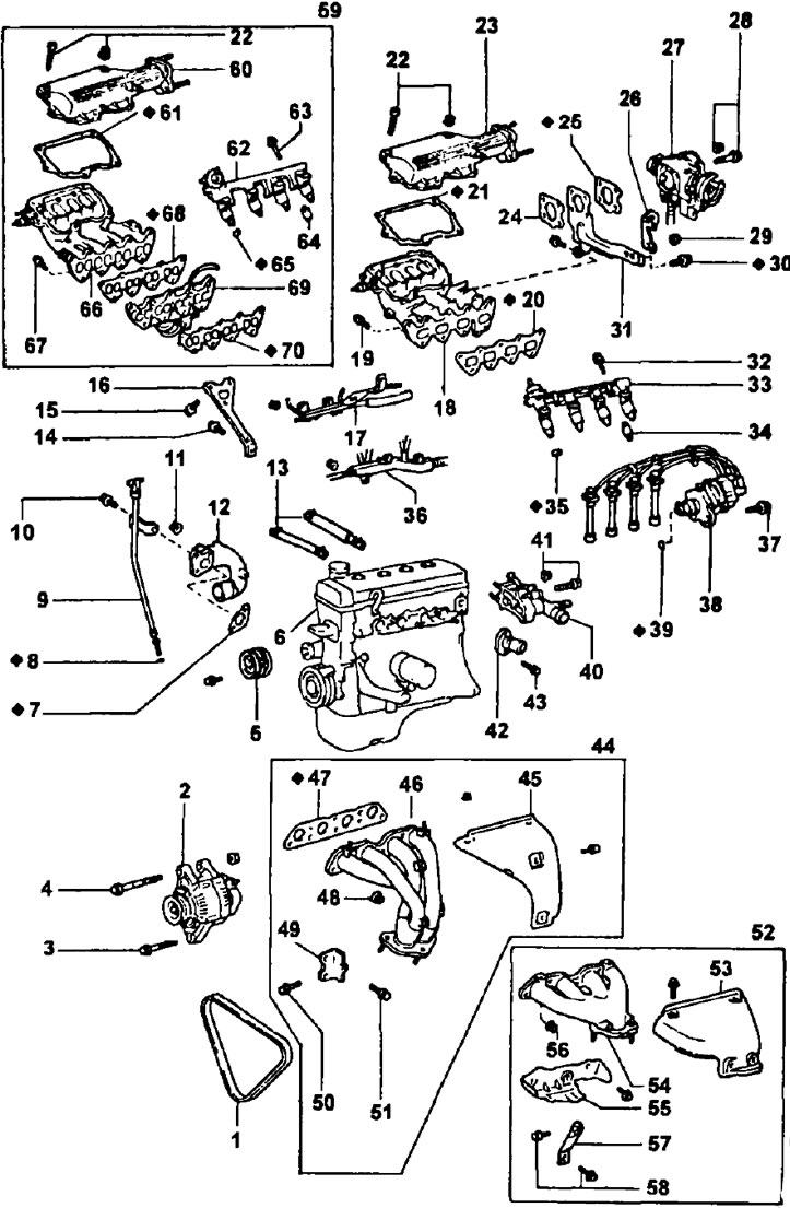
Removing the cylinder head. 1 - drive belt for the generator and coolant pump; 2 - generator; 3 - alternator lock bolt (М3=18 Nm); 4 - alternator mounting bolt (М3=58 Nm); 5 - coolant pump drive pulley; 6 - cylinder block with a block head in the assembly; 7 - gasket for the inlet pipe No. 2 of the coolant; 8 - sealing ring of the oil dipstick; 9 - oil dipstick assembly with guide; 10 - fixing bolt of the inlet pipe No. 2 of the coolant (M3=9.3 Nm); 11 - nut for fastening the inlet pipe No. 2 of the coolant (M3=15 Nm); 12 - inlet pipe No. 2 of the coolant; 13 - hoses of the forced crankcase ventilation system; 14 - a bolt of fastening of a support rack of an inlet collector (М3=39 Nm); 115 - intake manifold mounting bolt (М3=19 Nm); 16 - support rack of the intake manifold; 17 - air bypass tube; 18 - intake manifold; 19 - intake manifold mounting bolt (М3=19 Nm); 20 - intake manifold gasket; 21 - gasket cover of the air intake chamber; 22 - bolt for fastening the cover of the air intake chamber; 23 - air intake chamber cover; 24 - gasket between the flange of the inlet pipe of the air inlet chamber and the support post of the air inlet chamber; 25 - gasket under the throttle body; 26 - transport hook (eye) engine; 27 - throttle body; 28 - throttle body mounting bolt (М3=22 Nm); 29 - eye nut (М3=28 Nm); 30 - a bolt of fastening of a support rack of the chamber of an inlet of air (М3=28 Nm); 31 - support post of the air intake chamber; 32 - fuel manifold mounting bolt (M3=15 Nm); 33 - fuel manifold assembly with injectors; 34 - heat-insulating sleeve of the nozzle collector; 35 - nozzle insulator; 36 - engine wiring; 37 - a bolt of fastening of the integrated block of ignition (block contactless ignition system) M3=20 Nm; 38 - combined ignition unit (ignition distributor with ignition coil or contactless ignition system unit) with high voltage wires; 39 - sealing ring of the housing of the sensor-distributor of ignition; 40 - coolant inlet pipe and coolant supply unit to the cylinder head; 41 - bolt for fastening the coolant supply unit to the cylinder head (M3=20 Nm); 42 - branch pipe for draining coolant from the cylinder head; 43 - bolt for fastening the coolant outlet pipe (M3=15 Nm); 44 - details of the exhaust manifold for production engines with a catalytic converter of exhaust gases; 45 - exhaust manifold heat shield; 46 - exhaust manifold; 47 - exhaust manifold gasket; 48 - exhaust manifold mounting nut (М3=34 Nm); 49 - exhaust manifold support bracket; 50 - exhaust manifold support bracket bolt (М3=39 Nm); 51 - exhaust manifold support bracket bolt (М3=59 Nm); 52 - details of the exhaust manifold for other engines; 53 - upper heat-insulating casing of the exhaust manifold; 54 - exhaust manifold; 55 - lower heat-insulating casing of the exhaust manifold; 56 - exhaust manifold mounting nut (М3=34 Nm); 57 - exhaust manifold support; 58 - exhaust manifold mounting bolts (М3=39 Nm); 59 - details of the air intake chamber and intake manifold for an engine with a lean mixture combustion system; 60 - air intake chamber cover; 61 - gasket cover of the air intake chamber; 62 - fuel manifold assembly with injectors; 63 - a bolt of fastening of the general fuel line (collector) nozzles (M3=9.3 Nm); 64 - remote bushing (spacer) nozzle bolt; 65 - nozzle insulator; 66 - intake manifold; 67 - intake manifold mounting bolt (М3=19 Nm); 68 - intake manifold gasket; 69 - spacer (frame) additional shutters; 70 - gasket for the body of additional controlled dampers.
Note: In this engine, the intake manifold has 8 separate intake pipes connecting the air intake chamber (resonator) with each inlet valve, in the channels of the spacer directly in front of the inlet valves, additional dampers controlled by a servo mechanism are installed, partially blocking the channels at low loads.
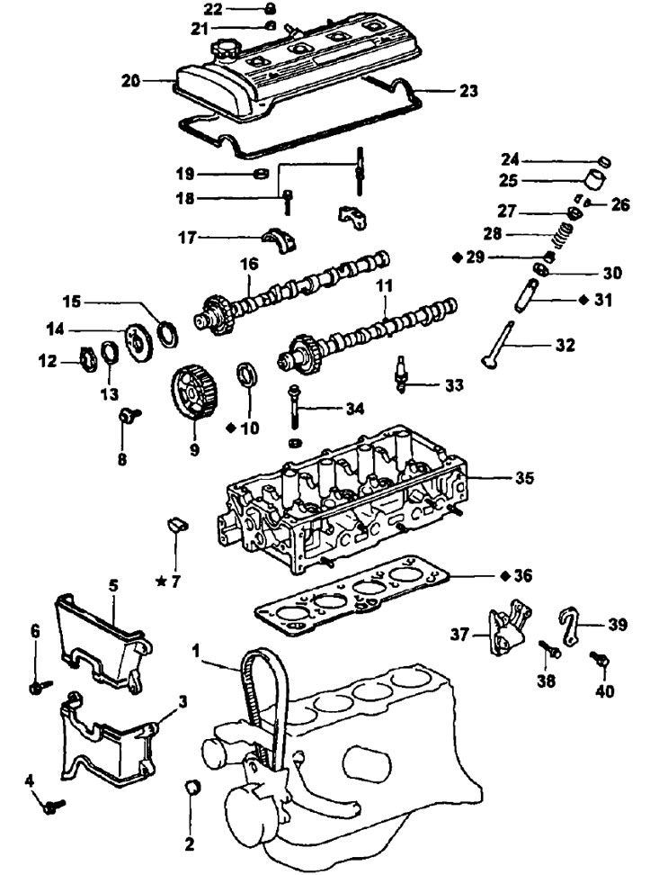
Removing the cylinder head (continuation). 1 - timing belt; 2 - rubber stopper; 3 - cover No. 2 of the timing belt; 4 - bolt for fastening the cover No. 2 of the timing belt (M3=7.4 Nm); 5 - cover No. 3 of the timing belt; 6 - bolt for fastening the cover No. 3 of the timing belt (M3=7.4 Nm); 7 - segment cap (part; installed with a pre-primer); 8 - a bolt of fastening of a pulley of a drive of a camshaft of final valves (М3=59 Nm); 9 - exhaust camshaft drive pulley; 10 - stuffing box; 11 - exhaust camshaft; 12 - lock (crimp) ring; 13 - wavy spring washer; 14 - auxiliary gear of the intake camshaft; 15 - leaf spring of the gear of the camshaft of the intake valves; 16 - intake camshaft; 17 - camshaft bearing cover; 18 - a bolt of fastening of a cover of the bearing of a camshaft (M3=13 Nm); 19 - gasket for the protective tube of the spark plug; 20 - timing cover (cylinder heads); 21 - sealing washer; 22 - cap nut; 23 - cylinder head cover gasket; 24 - adjusting washer (for adjusting the thermal clearance in valves); 25 - valve pusher; 26 - crackers; 27 - plate (holder) valve springs; 28 - valve spring; 29 - valve oil cap; 30 - support washer (saddle) valve springs; 31 - valve guide; 32 - valve; 33 - spark plug; 34 - a bolt of fastening of a head of the block of cylinders (М3=29 Nm); then sequentially tighten each bolt by 90°; then tighten each bolt again by 90°; 35 - cylinder head; 36 - cylinder head gasket; 37 - generator mounting bracket; 38 - alternator bracket bolt (M3=26 Nm); 39 - transport hook (eye) engine; 40 - eye bolt (М3=28 Nm).
Installing the cylinder head
1 Install the cylinder head.
- A) Lay a new cylinder head gasket, taking into account the position of the guides on the block.
- b) Lower the cylinder head onto the gasket.
Note: before installation, apply a light coat of engine mask on the bolt threads and under the bolt heads.
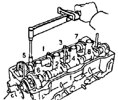
- V) Using a suitable tool, install and progressively tighten over several passes (at least 3) 10 head bolts in the sequence shown in the figure.
- Tightening torque - 29 Nm
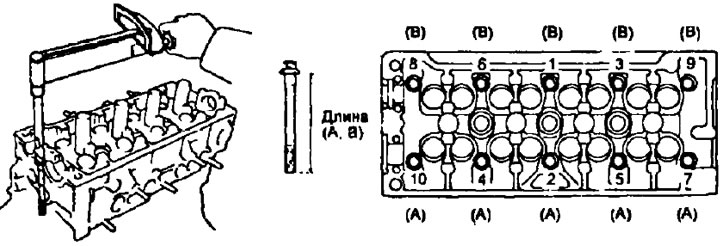
If the required torque is not reached when tightening the bolt, replace the bolt.
Note: The block head bolts have different lengths of 90mm and 108mm. When installing, be careful not to mix them up.
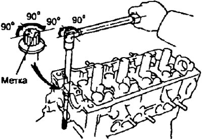
- G) Mark the edge of the bolt facing the front of the engine (side opposite the power take-off) paint as shown in the picture.
- d) Tighten all bolts in the sequence noted above by turning them 90°.
- e) Tighten all bolts again in the sequence noted above by another 90°.
- and) Make sure all bolt marks are oriented 180°from the original position.
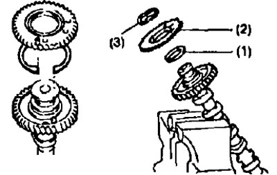
2. Assemble the intake camshaft.
- A) Secure the camshaft in a vise by clamping it on the hex section.
Note: Be careful not to damage the camshaft.
- b) Install the following parts:
- (1) camshaft gear spring
- (2) auxiliary gear,
- (3) wavy puck.
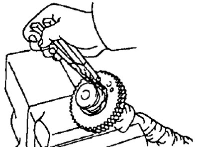
- V) Install the retaining ring with pliers.
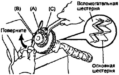
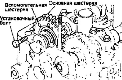
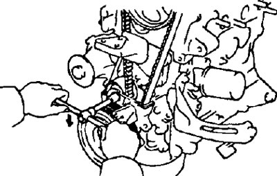
- G) Enter technological bolts (A) And (IN) into the camshaft sub gear locating hole
- d) Using a screwdriver, turn the camshaft sub gear clockwise and align the holes of the camshaft driven gear and the sub gear, then install the access bolt (WITH).
Note: Be careful not to damage the camshaft.
3. Install the intake and exhaust camshafts.
Attention: when installing camshafts, it must be taken into account that the axial clearance is very shallow, so the shafts must be laid in the bearing bed strictly horizontally, without distortion, in order to avoid jamming and / or damage to the shafts.
3.1 Install the exhaust camshaft.
- A) Apply grease to the end surfaces of the camshaft
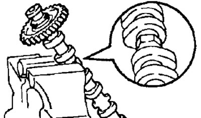
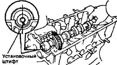
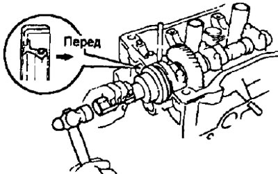
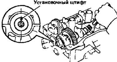
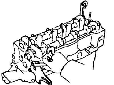
- b) Lay the exhaust camshaft into the cylinder head so that the dowel pin is slightly to the right of the vertical axis of the camshaft as shown. In this position, the cams of the 1st and 3rd cylinders equally press the pushers of the corresponding valves.
- V) Remove old sealant
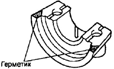
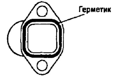
- G) Apply sealant to the #1 camshaft bearing cap as shown.
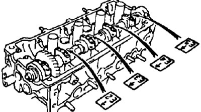
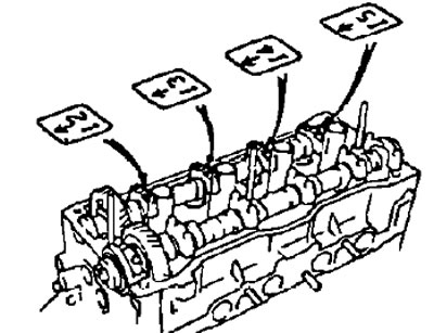
- d) Install the camshaft bearing caps on the corresponding journals in accordance with the numbers stamped on them, as shown in the figure; the arrows on the bearing caps must point towards the front of the engine (in the direction opposite to the power take-off).
- e) Apply engine oil to the threads and back of the bolt heads.
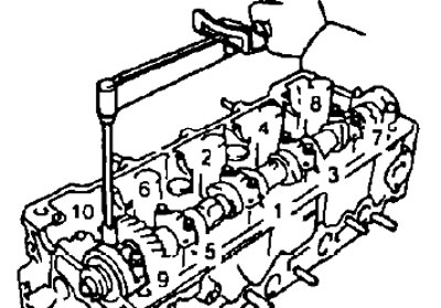
- and) Install and evenly tighten the bearing cap bolts in several passes in the order shown in the figure.
- Tightening torque - 13 Nm
- h) Apply grease to the seal lip.

- and) Using a suitable mandrel, install the camshaft oil seal
Note:
- The gland must be installed as shown in the figure.
- The gland is installed in the bore of the block head until it stops.
3.2 Install the intake camshaft.
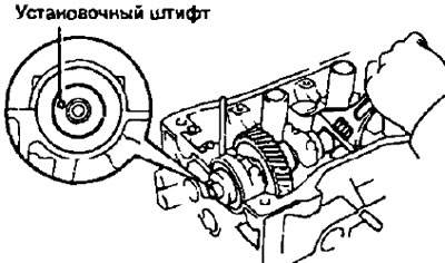
- A) Install the exhaust camshaft access pin so that it is slightly higher as shown in the figure
- b) Apply grease to the thrust (end) camshaft surface.
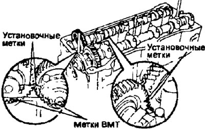
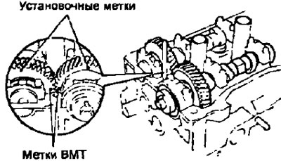
- V) Engage the gears of the intake and exhaust camshafts, aligning the timing marks on these gears with each other.
Note: The camshaft gears also have "timing marks" or TDC marks; do not confuse them with installation marks.
- G) Keeping the gears engaged, lay the intake camshaft in the bearing bed. In this position, the cams of the 1st and 3rd cylinders evenly press the pushers of the respective valves, which facilitates the installation of the camshaft.
- d) Install the camshaft bearing caps on the corresponding journals in accordance with the numbers stamped on them, as shown in the figure; the arrows on the bearing caps must point towards the front of the engine (in the direction opposite to the power take-off).
- e) Apply engine oil to the threads and back of the camshaft bearing cap bolt heads.
- and) Tighten the bearing cap bolts evenly in several passes in the order shown in the figure (final M3=13 Nm).
- h) Remove the technological bolt connecting the auxiliary and main gears of the intake camshaft.
- And) Install the cover of the 1st bearing of the intake camshaft with the arrow forward (towards the timing drive).
Attention: if the cover of the 1st bearing does not sit in place, use a screwdriver to move the camshaft back and forth along its axis.
- To) Tighten the bearing cap bolts evenly in several passes (final M3 = 13 Nm).
- l) Turn the exhaust camshaft clockwise by its hex part 1 turn (from TDC to BDC), so that the dowel pin is in the position shown in the figure.
- m) Make sure that the alignment marks of the gears of the exhaust and intake camshafts are in the uppermost position, and the TDC marks ("timing marks"), match each other as shown in the figure.
4. Check and adjust valve clearances (see "Checking and adjusting thermal clearances in valves").
5. Install the alternator mounting bracket and transport hooks (eyes) engine.
- Bolt tightening torque:
- generator bracket - 26 Nm
- rymov - 27 Nm
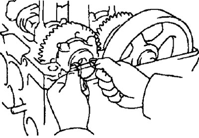
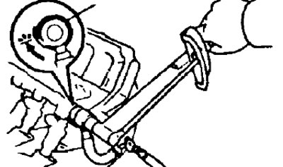
b. Install the camshaft sprocket.
- A) Align the camshaft locating pin with the locating groove of the pulley and install the pulley
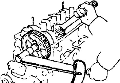
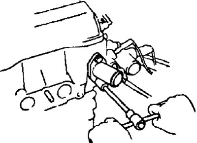
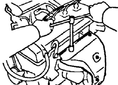
- b) Holding the camshaft by its hex part with a wrench, tighten the pulley mounting bolt (М3=59 Nm).
Note:
- Remove any remaining oil and water from the surface of the pulley and keep it always clean.
- When tightening the pulley mounting bolt, be careful not to damage the cylinder head with the wrench.
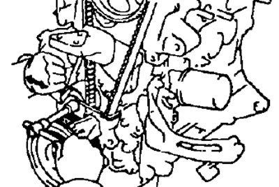
7. Install the timing belt.
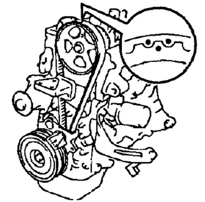
- A) Make sure the timing belt alignment marks are flush with the top surface of the #1 belt guard. Otherwise, it is necessary to change the engagement of the timing belt with the crankshaft toothed pulley.
- b) Align the marks on the belt and on the pulley made during dismantling and install the toothed belt.
8. Check the installation of the valve timing.
- A) Loosen the timing belt tensioner bolt.
- b) Rotate the crankshaft 2 turns from TDC to TDC.
Note: Always turn the crankshaft clockwise only.
- V) Check the valve timing, making sure that:
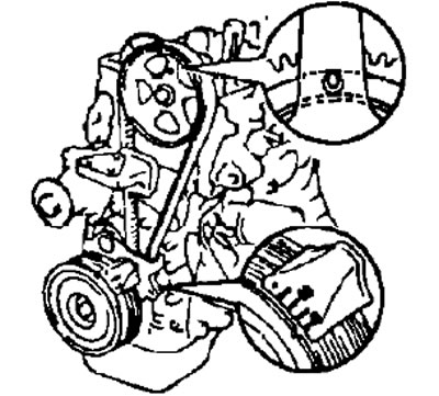
- the center of the small hole on the camshaft sprocket aligns with the mark on the 1st camshaft bearing cap as shown,
- mark on crankshaft pulley (alternator drive pulley and coolant pump) aligns with the corresponding mark on the timing belt guard. as it shown on the picture.
Note: If the marks on the pulleys do not match their mating marks, change (shift) engagement of the crankshaft toothed pulley with the timing belt and repeat the adjustment described in paragraphs 7 and 8 again.
- G) Tighten idler pulley set bolt (roller) timing belt (М3=37 Nm).
- d) Install the rubber plug on the #1 timing belt cover.
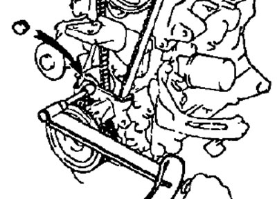
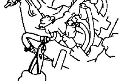
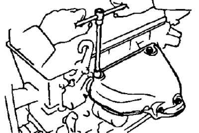
9. Check the tension of the timing belt.
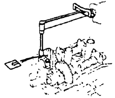
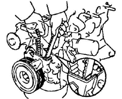
Check timing belt deflection. applying force as shown in the figure.
- Belt deflection (with a force of 20 N) — 5-6 mm
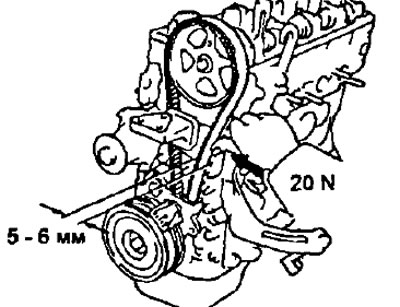
If the measured value is out of specification, adjust the tension by changing the position of the idler pulley (roller) timing belt.
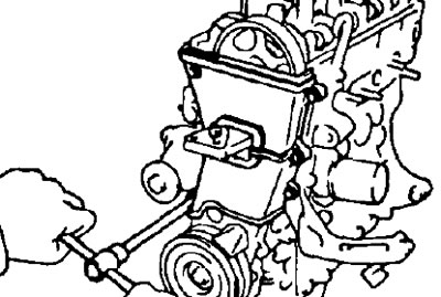
10. Install the protective covers No. 2 and No. 3 of the timing belt, securing them with 6 bolts (M3=7.4 Nm)
11. Install the segment (semicircular) plug.
- A) Remove old sealant.
- b) Apply fresh sealant to the segment plug as shown.
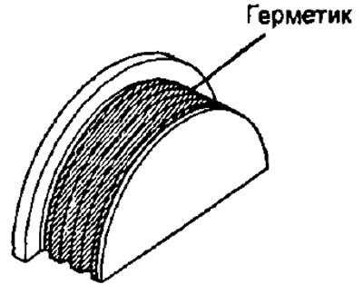
- V) Install the segment plug on the cylinder head.
12. Establish a cover of a head of the block of cylinders.
- A) Remove old sealant.
- b) Apply fresh sealant to the cylinder head as shown.
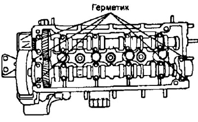
- V) Install the cylinder head cover gasket.
- G) Install the cover through the spacer rubber grommets and secure with the 3 cap nuts.
- Tightening torque - 6 Nm
13. Install the spark plugs using the special wrench
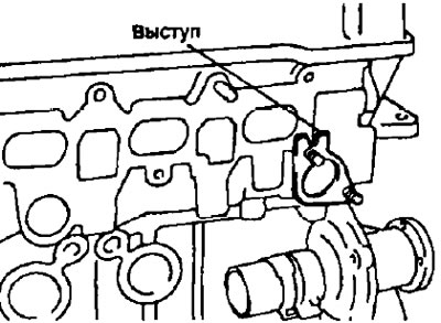
14. Install branch pipe No. 2 for supplying coolant.
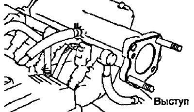
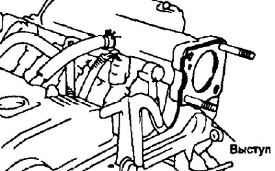
- A) Install a new gasket on the cylinder head seat, orienting it so that the tab on the gasket is facing up.
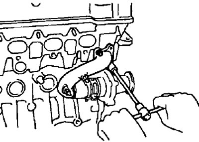
- b) Connect the hose to the pump.
- V) Connect the pipe to the cylinder head, securing it with 2 nuts (M3=15 Nm).
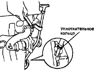
15. Install an oil level gauge ("oil dipstick") complete with guide.
- A) Install a new O-ring on the dipstick guide.
- b) Apply some soapy water to the O-ring.
- V) Install the dipstick assembly with the guide and secure it with a bolt (М3=9 Nm).
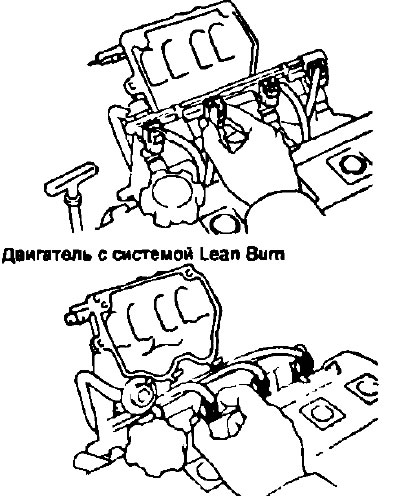
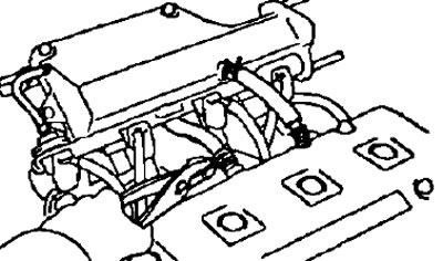
16. Install the intake manifold.
(4A-FE with serial version and 7A-FE)
Install the intake manifold with a new gasket and secure it with 7 bolts and 2 nuts. Tighten bolts and nuts evenly in several passes (final M3=19 Nm).
(4A-FE with Lean Burn)
- A) Install a new gasket on the outer mating plane of the auxiliary flap housing facing the intake manifold, and another new gasket on the mating plane of this housing facing the cylinder head.
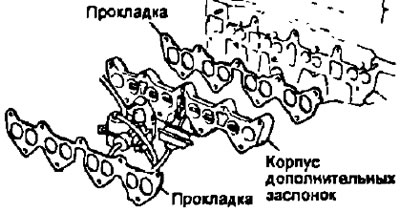
- b) Install intake manifold and secure with 7 bolts and 2 nuts Tighten bolts and nuts evenly in several passes (final M3=19 Nm).
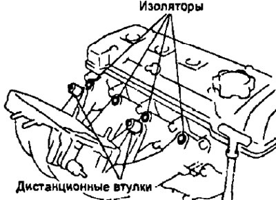
17. Install the injectors and the common fuel injector manifold on the intake manifold (Cm. "fuel injection system").
- A) Install a new sealing rubber bushing on the injector. Also install a new O-ring.
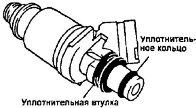
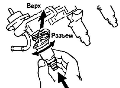
- b) Turning the injector left and right, install it in the intake hole of the injector manifold. Do this for all 4 injectors.
- V) Position the nozzles so that their connectors are oriented upwards, as shown in the figure.
- G) Install four new insulators and two (for engines with Lean bum system - three) heat-insulating sleeves in the corresponding places of the intake manifold.
- d) Install all four injectors together with their common fuel line (collector) to the appropriate location on the intake manifold.
- e) Temporarily install two bolts (for engines with Lean Bum system - three bolts), holding the injector manifold to the intake manifold.
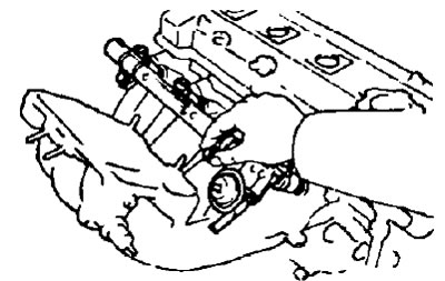
- and) Make sure the nozzles turn freely. A possible cause of injector sticking is improper installation of the O-rings: in this case, the injector O-rings must be replaced.
- h) Position the nozzles so that their connectors are oriented upwards, as shown in the figure.
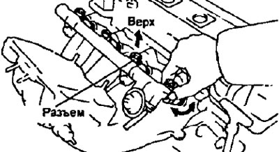
- And) Tighten two bolts (for engines with Lean Burn system - three bolts) common fuel line fasteners (collector) injectors to the intake manifold.
- Tightening torque for motors:
- with serial intake system - 15 Nm
- with Lean Vit system - 9 Nm
- To) Connect the injector connectors.
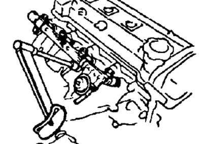
18. Connect the fuel supply hose to the common fuel line (collector) injectors by installing 2 new gaskets and tightening the bypass bolt (М3=29 Nm).
19. Connect the fuel return hose to the fuel differential pressure regulator.
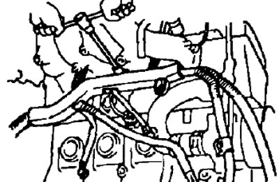
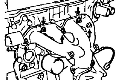
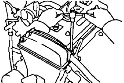
20. Install the air intake chamber cover (resonator).
- A) Install the air intake chamber cover with a new gasket. Using a 6 mm socket wrench, secure the intake chamber cover with 3 bolts and 2 nuts, tightening them in the sequence shown in the figure (М3=19 Nm).
- b) Connect the 2 hoses of the forced crankcase ventilation system and the vacuum transmission hose.
21. Connect the engine wiring to the intake manifold, securing the wiring harness with 3 bolts, and connect the connectors.
22. Install the air bypass pipe, securing it with a bolt and nut (М3=9 Nm)
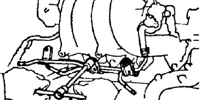
23. Install the intake manifold support by tightening the three bolts.
- Bolt tightening torque:
- with a socket head 12 mm - 19 Nm
- with a socket head 14 mm - 39 Nm
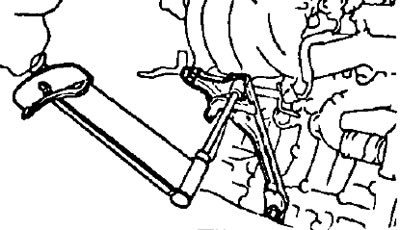
24. Install the air intake plenum support and right engine transport hook.
- A) Install a new gasket on the air inlet plenum flange with the tab on the gasket facing down.
- b) Install the air intake plenum support post and secure it with a bolt or two bolts (М3=28 Nm).
- V) Attach the air bypass tube (and fuel supply hose) bolt (or 2 bolts).
4A-FE serial version and 7A-FE.
4A-FE with Lean Burn
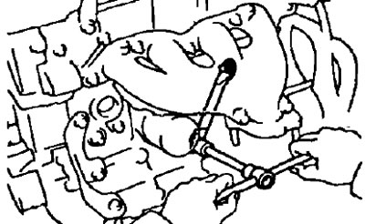
25. Install the throttle body.
- A) Install a new gasket on the air intake chamber flange (after installing the support stand on it) so that the protrusion on the gasket is oriented downwards.
- 6) Install the throttle body with 2 bolts and 2 nuts in the sequence shown in the figure (М3=22 Nm).
- V) Connect the air supply hose to the air bypass tube.
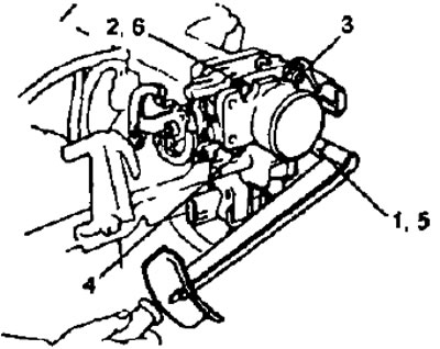
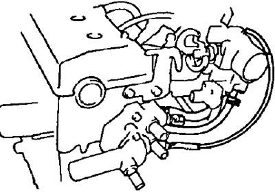
26. Establish knot of a supply of a cooling liquid to a head of the block of cylinders.
- A) Remove the old sealant and prevent oil from getting on the contact surfaces of the coolant supply unit and the cylinder head:
- Use a sharp blade and scraper to remove sealant residue from contact surfaces and sealing grooves.
- Thoroughly clean all components by removing material residues,
- Use solvent to clean both contact surfaces
- b) Apply new sealant to the grooves in the contact surface of the coolant inlet assembly.
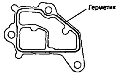
Notes:
- When applying sealant, the nozzle of the tube should be adjusted to the diameter of the extruded sealant of 2-3 mm.
- Excessive amount of sealant on the contact surfaces is unacceptable, be especially careful near the openings of the oil channels
- The mating surfaces must be joined within 15 minutes. after applying the sealant, otherwise the sealant must be removed and applied fresh.
- At the end of the application of sealant, the nozzles must be removed from the tube, and the tube with sealant must be tightly closed.
- V) Secure the coolant inlet assembly with a bolt and two nuts (M3=20 Nm).
- G) Connect the hose of the thermopneumatic relay of the fuel vapor recovery system (from fitting "R" throttle body) and coolant bypass hose.
27. Install the distributor of the ignition system or the combined block of the ignition system (block contactless ignition system) (see chapter "Ignition system" subsection "Installing a Distributor or Combined Ignition Unit").
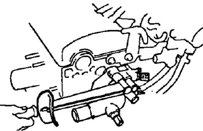
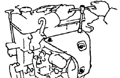
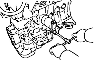
28. Install the coolant outlet pipe.
Secure the coolant outlet pipe with 2 bolts (M3=15 Nm).
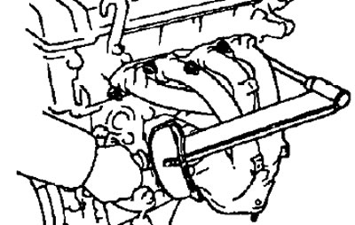
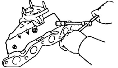
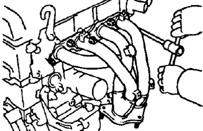
29. Install the exhaust manifold.
(4A-FE serial version)
- A) Install the exhaust manifold with a new gasket, securing it with 5 nuts. Tighten the nuts evenly over several passes (М3=34 Nm).
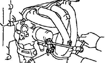
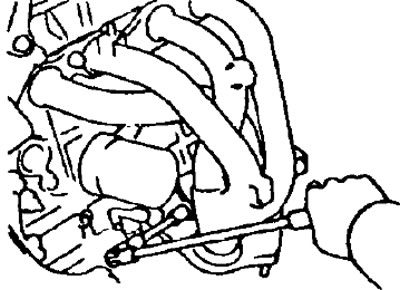
- b) Install the exhaust manifold support with the 2 bolts. Gradually tighten the bolts.
- Bolt tightening torque k:
- exhaust manifold - 39 Nm
- cylinder block - 53 Nm
- V) Install the upper exhaust manifold shield with 3 bolts and 2 nuts (M3=9.3 Nm).
(4A-FE engine modifications)
- A) Install the lower exhaust manifold guard with 3 bolts (M3=9.3 Nm).
- b) Install the exhaust manifold with a new gasket, securing it with 5 nuts. Tighten the nuts evenly over several passes (final M3=34 Nm).
- V) Install the exhaust manifold support with the 2 bolts. Gradually tighten the bolts (М3=39 Nm).
- G) Install the upper exhaust manifold shield with four bolts (M3=9.3 Nm)
(7A-FE)
- A) Install the exhaust manifold support with the two bolts.
- b) Install the exhaust manifold with a new gasket, securing it with 5 nuts. Tighten the nuts evenly over several passes (final M3=34 Nm).
- V) Tighten the strut-to-exhaust manifold bolt (М3=34 Nm).
- G) Install the top heat shield with 3 bolts and 2 nuts (M3=9.3 Nm).
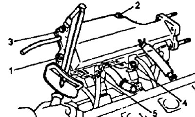
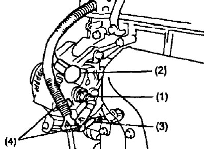
30. Connect the motor wiring.
- A) Install the electrical wiring protective cover. fix it with 2 bolts.
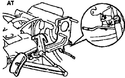
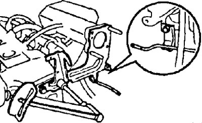
- b) Connect the following wires, connectors and clips:
- (1) generator connector;
- (2) generator wire;
- (3) emergency oil pressure sensor connector;
- (4) two wire ties.
31. Install the coolant pump pulley and alternator and coolant pump drive belt.
- A) Temporarily install the water pump pulley with 4 bolts.
- b) Install the alternator and coolant pump drive belt and tighten it slightly using the adjusting bolt. The locking bolt should only be tightened after adjusting the belt tension.
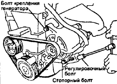
- V) Tighten the 4 coolant pump pulley bolts.
32. Adjust the tension of the alternator drive belt and coolant pump.
33. Fill the cooling system with coolant (see chapter "Cooling system").
34. Connect a wire to the negative plug of the storage battery.