
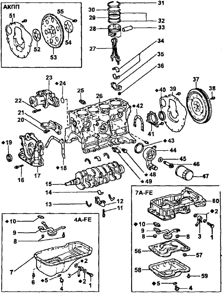
Cylinder block. 1 - fitting bolt (М3=34 Nm); 2 - fitting gaskets; 3 - oil cooler oil pipe fitting; 4 - oil drain plug (М3=34 Nm); 5 - plug gasket; 6 - bolt (M3=4.9 Nm); 7 - oil pan (4A-FE); B - bolts (M3=9.3 Nm); 9 - oil receiver with a strainer; 10 - oil receiver gasket; 11 - a bolt of fastening of a cover of the radical bearing (М3=60 Nm); 12 - crankshaft main bearing caps; 13 - persistent half rings; 14 - crankshaft bearing shells; 15 - crankshaft; 16 - a bolt of fastening of the case of the oil pump (М3=21 Nm); 17 and 18 - housing and gasket of the oil pump housing; 19 - crankshaft toe seal; 20 - a bolt of fastening of the right support of the engine (М3=51 Nm); 21 - right engine support; 22 - bolt (M3=14 Nm); 23 - coolant pump; 24 - sealing ring; 25 - knock sensor (М3=37 Nm); 26 - cylinder block; 27 - connecting rod; 28 - piston; 29 - oil scraper ring expander; 30 - compression ring No. 2; 31 - compression ring No. 1; 32 - scrapers of the oil scraper ring; 33 - piston pin; 34 - liners of connecting rod bearings of the crankshaft; 35 - cover of the crank head of the connecting rod; 36 - nut of fastening of a cover of a crank head of a rod (the first stage М3=29 Nm; then turn another 90°); 37 - flywheel; 38 - flywheel mounting bolt (М3=78 Nm); 39 - back plate (lid) cylinder block (clutch housing cover); 40 - oil seal of the crankshaft shank; 41 - crankshaft shank oil seal holder; 42 - gasket holder for the crankshaft shank; 43 - oil filter bracket gasket; 44 - oil filter bracket; 45 - flat washer; 46 - bolt fitting (bypass bolt); 47 - oil filter; 48 - plug for draining the coolant from the cylinder block (М3=34 Nm); 49 - emergency oil pressure sensor; 51 - back plate (lid) cylinder block; 52 - front spacer; 53 - torque converter drive plate; 54 - rear spacer; 55 - bolt (М3=64 Nm); 56 - oil softener (7A-FE); 57 - nut (M3=7.8 Nm); 58 - lower part of the oil pan (7A-FE); 59 - bolt (M3=4.9 Nm); 60 - upper part of the oil pan (7A-FE).
Preparation for disassembly of the cylinder block
1. (Models with manual transmission)
- A) Remove clutch cover and clutch disc
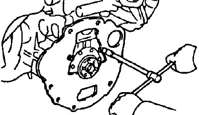
- b) Remove flywheel by removing 6 bolts.
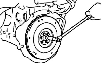
Note: before removing the flywheel or torque converter drive plate, set marks so as not to disturb the balance when installing them.
(Models with automatic transmission)
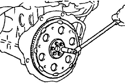
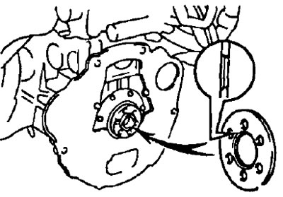
Remove the torque converter drive plate along with the front and rear spacers by removing the 6 bolts.
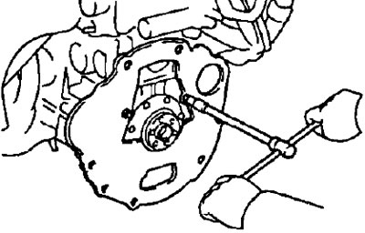
2. Remove the back plate (cover) cylinder block by removing 2 bolts.
3. Install the engine on the stand (machine) for disassembly.
4. (Models with air conditioning) Remove the air conditioning compressor.
5. Remove the toothed belt and toothed pulleys of the timing drive (see "Removing the timing belt").
6. Remove the cylinder head (see "Removing the cylinder head").
7. Remove the alternator and alternator tension bar by unscrewing 2 bolts.
8. Remove the right engine mount by unscrewing 3 bolts
9. Remove the coolant pump by unscrewing the 3 bolts and removing the O-ring (see chapter "Cooling system").
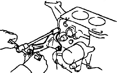
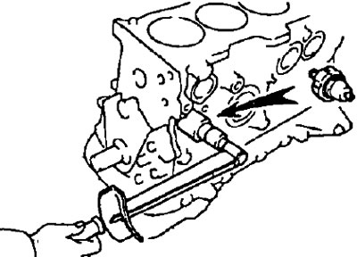
10. Remove the oil filter using a suitable wrench as shown.
11. (Only for engines with oil cooler)
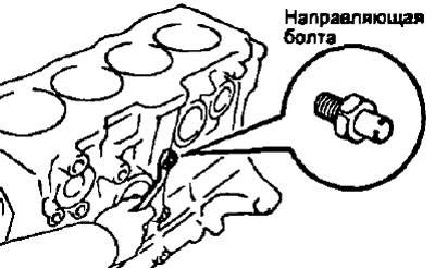
Remove the oil filter bracket by unscrewing the bypass bolt, removing the flat washer and removing (after removing bracket): O-ring and bolt guide.
 |  |
12. Remove the plug or cock to drain the coolant from the cylinder block.

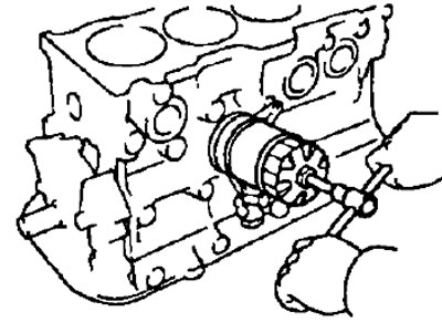
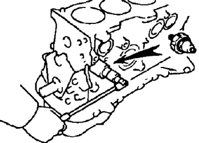
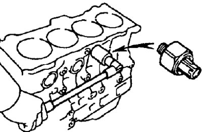
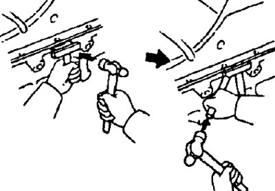
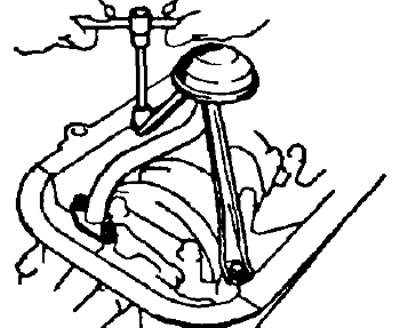
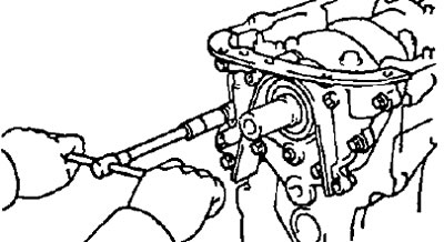
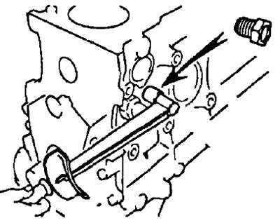
13. Using a suitable tool, remove the emergency oil pressure switch or oil pressure switch.
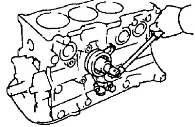
14. Using a suitable tool, remove the knock sensor.
15. (4A-FE)
Remove the oil pan and oil receiver with strainer
- A) (Only for engines with oil cooler) Remove the oil cooler pipe fitting.
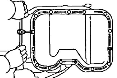
- b) Remove the pallet by unscrewing 19 bolts and 2 nuts.
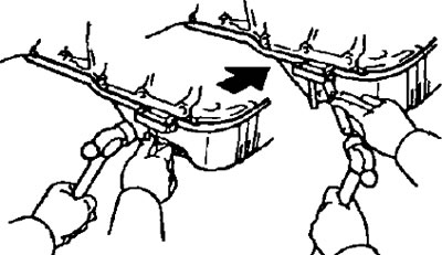
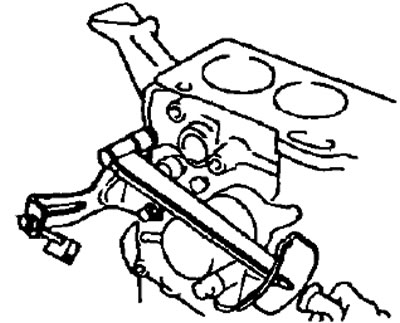
- V) Insert a sharp blade between the mating surfaces of the cylinder block and sump, cut the seal and remove the sump.
Notes:
- Be careful not to damage the sump flange.
- Do not use a similar method when removing the oil pump and crankshaft shank oil seal holder
- G) Having unscrewed 2 bolts and 2 nuts, remove the oil receiver with a strainer.
(7A-FE)
Remove the bottom of the oil pan, the oil separator, the oil pickup with strainer and the top of the oil pan.
- A) (Oil cooler engines) Remove the oil cooler pipe fitting.
- b) Remove the lower part of the oil pan by removing 13 bolts and 2 nuts.
- V) Insert a sharp blade between the mating surfaces, cut off the seal and remove the bottom of the oil pan.
Notes:
- Be careful not to damage the sump flange.
- Do not use this method when removing the upper part of the oil pan, oil pump and crankshaft shank oil seal retainer.
- G) Having unscrewed 2 bolts and 2 nuts, remove the oil receiver with a strainer.
- d) After unscrewing 3 nuts, remove the oil receiver with strainer and gasket.
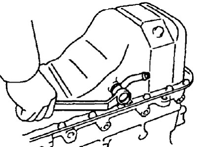
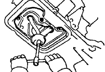
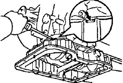
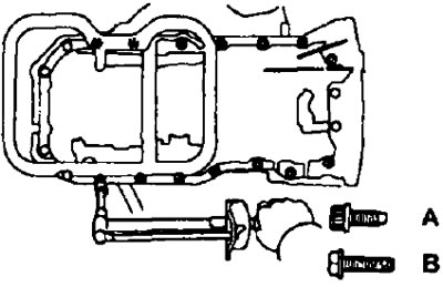
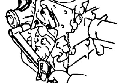
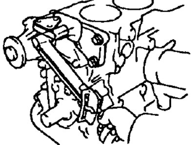
- e) Remove 6 bolts. Using the special tool, remove the 14 bolts and remove the upper part of the oil pan.
If the top of the oil pan cannot be removed, use a screwdriver as a lever as shown in the illustration.
16. Having unscrewed 7 bolts, remove the oil pump housing together with the gasket.
Final assembly
1. Install the oil pump.
- A) Place a new gasket on the surface of the cylinder block that mates with the oil pump housing.
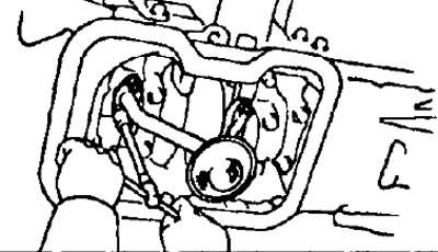
- b) Align the pump main rotor keyway with the large crankshaft key and fit the pump onto the shaft as shown.
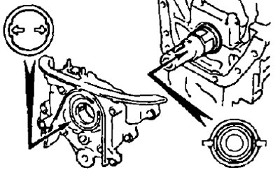
- V) Bolt the pump (М3=21 Nm).
- Please note that bolts of different lengths are used (see pictures):
- long bolts - 35 mm
- other bolts - 25 mm
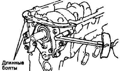
4A-FE | 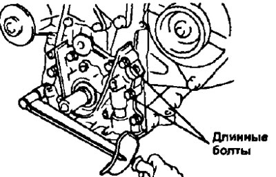
7A-FE |
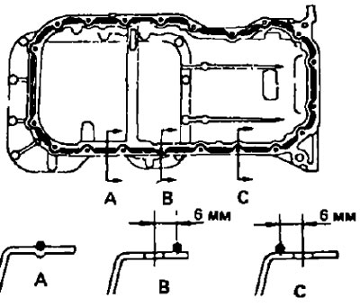
2. (4A-FE)
Install the oil pan and oil pickup with strainer.
- A) Install the oil receiver, after installing a new gasket, and then tighten the mounting bolts and nuts (M3=9.3 Nm).
- b) Remove the old sealant from the surfaces of the sump and block connector, being careful not to damage the surfaces of the sump and cylinder block, clean the contact surfaces with a solvent.
Note: Do not use solvents that may damage painted surfaces.
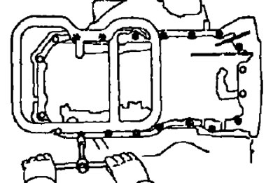
- V) Apply fresh sealant to the surface of the pan as shown.
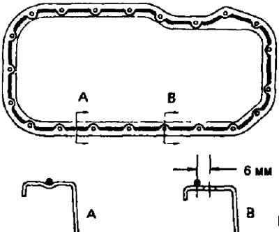
Notes:
- The hole in the tube should ensure that the diameter of the extruded sealant is 3 - 5 mm
- The parts must be connected within 5 minutes after applying the sealant, otherwise the sealant must be removed and fresh applied.
- At the end of the application of sealant, the nozzle of the tube must be removed and cleaned of traces of sealant, and the tube must be tightly closed.
- G) Secure the pallet with bolts and nuts.
- Tightening torque - 5 Nm
- d) (Oil cooler engines) Install fitting (with 2 new gaskets) oil cooler hose and bypass bolt by tightening it.
- Tightening torque - 34 Nm
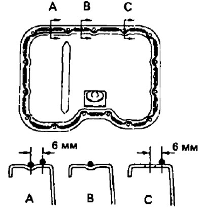
(7A-FE)
Install the bottom of the oil pan, the oil damper, the oil receiver with strainer and the top of the oil pan.
- A) Remove old sealant from contact surfaces and clean with solvent.
- b) Apply sealant (see paragraph "V" paragraph "2") onto the surface of the top of the pallet, as shown in the figure.
- V) Install the top of the oil pan. Using a special tool, secure it with 14 new bolts "A".
- Tightening torque - 16 Nm
- G) Install and tighten 6 bolts "IN".
- Tightening torque - 8 Nm
- d) Install the oil receiver with a new gasket and secure it with 3 nuts.
- Tightening torque - 9 Nm
- e) Install the oil separator by securing it with 2 bolts and 2 nuts.
- Tightening torque - 8 Nm
- and) Install the bottom of the oil pan.
- Remove old sealant from contact surfaces and clean with solvent.
Note: Do not use solvent. which can damage painted surfaces.
- Apply sealant (see paragraph "V" paragraph "2") on the surface of the pallet, as shown in the figure.
- Install the bottom of the oil pan with 13 bolts and 2 nuts (M3=5 Nm).
- e) (Oil cooler engines) Install oil cooler hose fitting with 2 new gaskets and tighten bypass bolt (М3=34 Nm)
3. Install the knock sensor using a suitable tool (М3=37 Nm).
4. Install the emergency oil pressure switch or oil pressure switch.
- A) Apply glue to 2-3 sensor threads
- b) Using a suitable tool, wrap the sensor as shown in the figure.
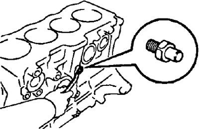
5. Install the coolant drain plug.
- A) Apply glue to 2-3 cork threads (see paragraph 4 of this section).
- b) Wrap the cork (М3=34 Nm).
6. (Engines with oil cooler) Install the oil filter bracket (see chapter "Lubrication system").
- A) Install the bracket guide bolt.
- b) Install a new O-ring under the oil filter bracket.
- V) Install oil filter bracket with flat washer and bypass bolt (М3=54 Nm).
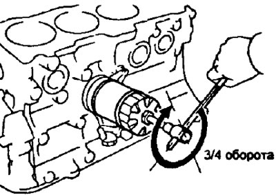
7. Install the oil filter.
- A) Clean the contact surface where the oil filter is installed.
- b) Lubricate the filter rubber seal with fresh engine oil.
- V) Screw on the filter by hand until its gasket contacts the seating surface. Then, using a suitable tool, tighten the filter an additional 3/4 turn.
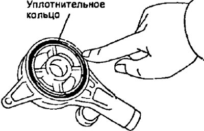
8. Install the coolant pump.
- A) Install a new O-ring to the cylinder block as shown.
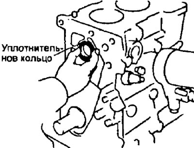
- b) Bolt the coolant pump (M3=14 Nm).
9. Install the right engine mount and secure it with 3 bolts (М3=51 Nm).
10. Install the alternator tension bar by securing it with 2 bolts (MZ=39 Nm).
11. Install the cylinder head (see section "Installing the cylinder head").
12. Install the timing belt and pulleys (see section "Timing belt installation").
13. Install the ignition distributor or integrated ignition unit.
14. (Models with air conditioning) Install the A/C compressor mount.
15. Remove the engine from the mounting stand.
16. Install motor backplate and secure with 2 bolts (M3=5.5 Nm).
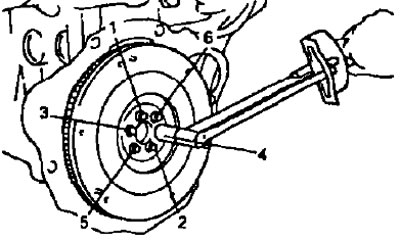
17. (Models with manual transmission) Install the flywheels and evenly in several passes, tighten the flywheel mounting bolts in the sequence shown in the figure (final M3=78 Nm).
18. (Models with automatic transmission) Install the torque converter drive plate.
- A) Install the front spacer onto the crankshaft with the chamfered side of the spacer facing towards the shaft as shown.
- b) Install the drive plate and rear spacer onto the crankshaft.
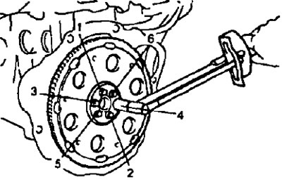
- V) Screw in and evenly, in several passes, tighten the fixing bolts in the sequence shown (final M3=64 Nm).
19. (Models with manual transmission) Install the clutch disc and cover.
Note: If necessary, check the clutch assembly before installation.