
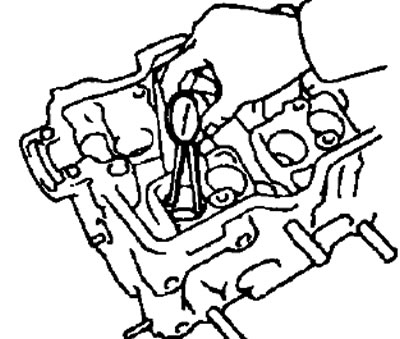
- A) Turning the crankshaft, sequentially set the pistons to TDC. With a scraper, clean the surfaces of the piston bottoms from carbon deposits.
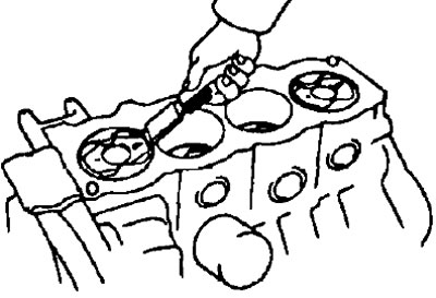
- b) Using a scraper, remove the remnants of the head gasket on the surface of the cylinder block connector.
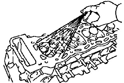
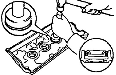
- V) Use compressed air to remove carbon deposits and head gasket residue from surfaces, bolt holes.
Note: When using compressed air, be careful not to get dirt particles in your eyes.
2. Clean the cylinder head.
- A) Clean the surface of the head of the block from the remnants of the head gasket.
Note: Be careful not to damage the gasket mating surface of the block head.
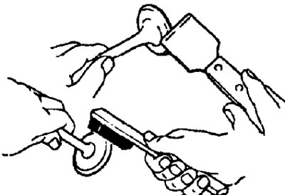
- b) Clean the surfaces of the combustion chambers of the block head with a wire brush, removing any remaining carbon deposits.
- V) Clean the holes in the head guide bushings with a brush and solvent.
- G) Clean the surface of the cylinder head (mating with the surface of the cylinder block), using a soft brush and solvent.
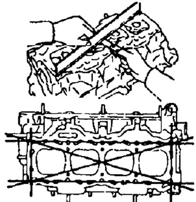
3. Check the cylinder head.
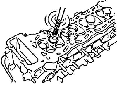
A) With a precision ruler and a flat feeler gauge, as shown in the figure, check the flatness of the working surfaces of the cylinder head mating:
- with the surface of the cylinder block.
- with the surfaces of the inlet and outlet pipelines.
 |  |
Maximum allowable surface non-flatness:
- gas joint:
- 2C, 2C-T, 3S-GE - 0.20 mm
- 3S-FE, 4S-FE, 4A-FE, 5E-FE, 7A-FE - 0.05mm
- mating intake manifold:
- 2C, 2C-T, 3S-GE - 0.20 mm
- 3S-FE, 4S-FE - 0.08mm
- 4A-FE, 7A-FE - 0.10 mm
- 5E-FE - 0.05 mm
- mating exhaust manifold:
- 2C, 2C-T - 0.20 mm
- 3S-FE, 4S-FE - 0.08mm
- 3S-GE - 0.30 mm
- 4A-FE, 7A-FE - 0.10mm
- 5E-FE - 0.05 mm
If the amount of non-flatness exceeds the maximum allowable. replace the cylinder head or grind it.
- 6) Using a penetrating dye, check for cracks in the combustion chambers, inlet and outlet ports, and at the gas interface. If there are cracks, replace the cylinder head or weld it (followed by polishing).
4. Clean the valves.
- A) Use a scraper to remove carbon deposits from the valve disc.
- b) Completely clean the valve with a brush.
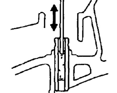
5. Check valve stem diameters and valve guide bores.
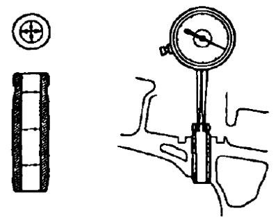
- A) Measure the inside diameter of the valve guides with a bore gauge.
- Sleeve inner diameter:
- 2C, 2C-T - 8.010-8.030 mm
- 3S-FE, 4S-FE, 4A-FE, 5E-FE, 7A-FE - 6.010-6.030mm
- 3S-GE - 6.000-6.018 mm
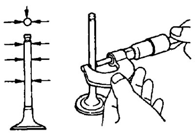
- b) Measure the diameter of the valve stem with a micrometer.
- Valve stem diameter:
- inlet valve:
- 2C, 2C-T - 7.975-7.990 mm
- 3S-FE, 4S-FE, 4A-FE, 5E-FE and 7A-FE - 5.970-5.985 mm
- 3S-GE - 5.960-5.975 mm
- Exhaust valve:
- 2C, 2C-T - 7.960-7.975 mm
- 3S-FE, 4S-FE, 4A-FE, 5E-FE and 7A-FE - 5.965-5.980 mm
- 3S-GE - 6.955-5.970 mm
- inlet valve:
- V) Find the gap between the valve stem and guide by measuring the difference between the valve stem diameter and the inner diameter of the valve guide.
- Rated oil clearance: inlet valve:
- 2C, 2C-T - 0.020-0.055 mm
- 3S-FE, 4S-FE, 4A-FE, 5E-FE and 7A-FE - 0.025-0.060mm
- 3S-GE - 0.025-0.058 mm
- 2S.2S-T - 0.035-0.070 mm
- 3S-FE, 4S-FE, 4A-FE, 5E-FE and 7A-FE - 0.030-0.065mm
- 3S-GE - 0.030-0.063 mm
- Rated oil clearance: inlet valve:
- Max oil clearance:
- intake valve - 0.08 mm
- exhaust - 0.10 mm
If the clearance is greater than the maximum, replace the valve and guide bushing.
6. If necessary, replace the valve guides.
- A) Gradually heat the cylinder head in a water bath to a temperature of 80-100°C.
- b) Using a drift and hammer, press out the guide bushing.
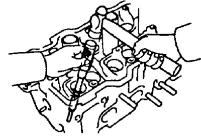
- V) Using a inside gauge, measure the diameter of the bore under the guide in the cylinder head housing.
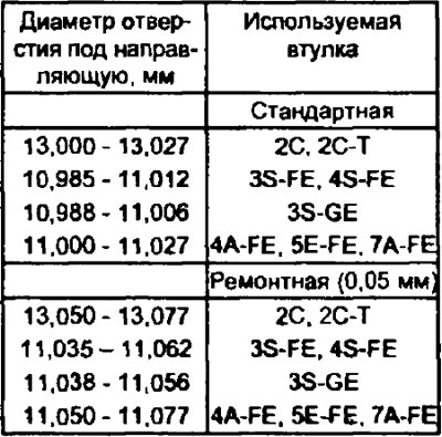
- G) Choose a new size (standard or repair by 0.05 mm) outside diameter of the valve guide.
If the diameter of the guide hole in the head housing is larger than:
- 2C, 2C-T - 13.027 mm
- 3S-FE, 4S-FE - 11.012mm
- 3S-GE - 11.006 mm
- 4A-FE, 5E-FE, 7A-FE - 11.027mm
then bore the hole for the guide to the diameter:
- 2C, 2C-T - 13.050-13.077 mm
- 3S-FE, 4S-FE - 11.035 - 11.062 mm
- 3S-GE - 11.038-11.056 mm
- 4A-FE, 5E-FE and 7A-FE - 11.050-11.077 mm
If the diameter of the hole for the guide in the block head housing exceeds the repair size, then replace the cylinder head.
The size of the outer diameters of the bushings of the inlet and outlet valves, choose depending on the diameters of the holes for the guides (see table).
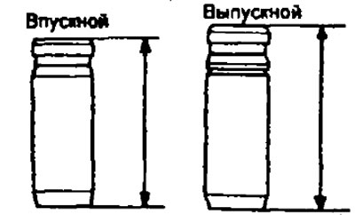
Note: on 2C, 2C-T, 3S-FE, 5E-FE engines, the intake and exhaust valve guides have different sizes.
Guide bushings:
- inlet valves:
- 2C, 2C-T - 46.0 mm
- 3S-FE, 5E-FE - 38.5mm
- exhaust valves:
- 2C, 2C-T - 50.0 mm
- 3S-FE, 5E-FE - 40.5 m
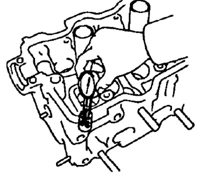
- d) Heat the cylinder head in a water bath to a temperature of 80-100°C.
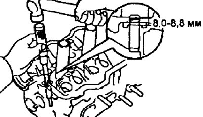
- e) Install the valve guide. Using a drift and hammer, install the new valve guide so it protrudes from the cylinder head at:
- 4A-FE, 7A-FE, 5E-FE - 12.7-13.1 mm
- 2C, 2C-T - 17.3-18.1 mm
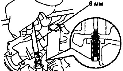
- and) Using a 6 mm reamer (3S-FE, 3S-GE, 4S-FE, 4A-FE, 5E-FE and 7A-FE) or 8 mm (2S, 2S-T), ream the inner hole of the guide to ensure the correct clearance between the guide and the valve stem (see point 5 (V)).
7. Check and lap the valves.
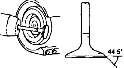
- A) Grind the valves until traces of soot and scratches are eliminated.
- b) Ensure that the lapped bevel of the valve forms a 44.5°angle with respect to a plane perpendicular to the axis of the stem.
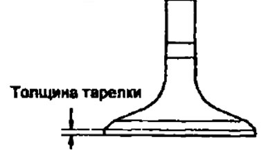
- V) Check valve disc thickness.
- Standard plate thickness:
- 3S-FE, 4S-FE, 3S-GE, 4A-FE, 5E-FE, 7A-FE - 0.8-1.2 mm
- 2S, 2S-T
- intake valve - 1.41 mm
- exhaust valve - 1.51 mm
- Minimum plate thickness:
- 3S-FE, 4S-FE, 3S-GE, 4A-FE, 5E-FE, 7A-FE - 0.5mm
- 2S, 2S-T
- intake valve - 0.9 mm
- exhaust valve - 1.0 mm
If the poppet thickness of the cylindrical part of the poppet is less than the minimum allowable value, replace the valve.
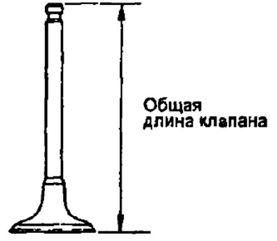
- G) Check overall valve length
- Nominal length:
- Inlet valve:
- 2C - 105.70 mm
- 2S-T - 105.50-05.90 mm
- 3S-FE - 97.60 mm
- 4S-FE - 100.60mm
- 3S-GE - 105.50mm
- 4A-FE, 7A-FE - 87.45 mm
- 5E-FE - 93.45 mm
- Exhaust valve:
- 2C - 105.35 mm
- 2S-T - 105.15-105.55 mm
- 3S-FE - 98.45mm
- 4S-FE - 100.45mm
- 3S-GE - 99.55mm
- 4A-FE, 7A-FE - 87.84mm
- 5E-FE - 93.89 mm
- Inlet valve:
- Minimum overall length:
- Inlet valve:
- 2C, 2C-T - 105.20 mm
- 3S-FE - 97.10 mm
- 4S-FE - 100.10mm
- 3S-GE - 104.80mm
- 4A-FE, 7A-FE - 86.95mm
- 5E-FE - 92.95mm
- Exhaust valve:
- 2C, 2C-T - 104.85 mm
- 3S-FE - 98.00 mm
- 4S-FE - 99.95 mm
- 3S-GE - 98.85mm
- 4A-FE, 7A-FE - 87.35mm
- 5E-FE 93.39mm
- Inlet valve:
If the overall length is less than the minimum, replace the valve.
- d) Check the condition of the valve faces for wear.
If the valve face is worn, regrind the valve face or replace the valve.
Note: when regrinding, do not reduce the overall length of the valve beyond its minimum allowable value.
8. Check and clean the valve seats.
- A) Use a 45°carbide cutter to grind the valve seats, removing only the minimum amount of metal to clean the seat bevels.
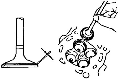
- b) Check for proper seating of the valve.
Apply a thin layer of white to the bevel of the valve. Press the valve face against the seat, but do not rotate the valve. Then remove the valve and inspect the valve seat and bevel.
If the paint remains around the entire circumference (360°) chamfers of the valve, the valve is concentric. Otherwise, replace the valve.
If the paint appears around the entire circumference (360°) valve seats, guide (sleeve) valves and valve seat are concentric. Otherwise, regrind the bevel.
Make sure that the contact patch is located in the middle part of the valve face and has a width of:
- 3S-FE, 4S-FE, 3S-GE, 4A-FE, 5E-FE, 7A-FE - 1.0-1.4 mm
- 2C, 2C-T - 1.2-1.6 mm
Otherwise, adjust the chamfer as follows:
If the contact patch is too high on the valve face, use 30°and 45°taper cutters to regrind the seat.
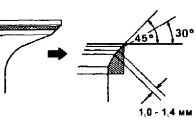
If the contact patch is too low on the valve face, use 75°and 45°or 60°and 45°taper cutters to regrind the seat as shown.
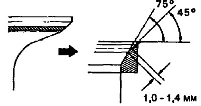
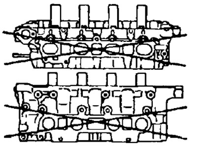
3S-GE, 3S-FE, 5E-FE | 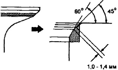
2C, 2C-T, 4A-FE, 7A-FE, 4S-FE |
- G) Hand lap the valve and valve seat using abrasive paste.
- d) After lapping, clean the valve and valve seat.
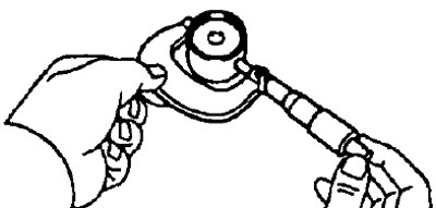
9. Check valve springs.
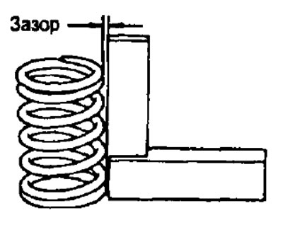
- A) Using a metal square (90°), check that the valve spring is not perpendicular, as shown in the illustration.
- The maximum allowable non-lerpendicularity is - 2.0 mm
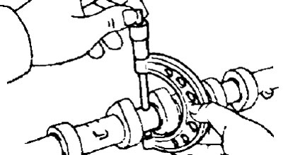
- b) Use a caliper to measure the free length of the spring in its free state.
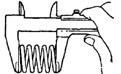
Valve Spring Length:
- 2G, 2C-T - 47.50 mm
- 3S-FE, 4S-FE - 40.95-42.00 mm
- 3S-GE - 44.43 mm
- 4A-FE, 7A-FE - 38.57mm
- 5E-FE - 39.80 mm
If the spring length is out of specification, replace the valve spring.
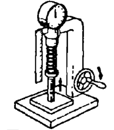
- V) Using a spring tester, measure the force required to compress the spring to its installation length.
The force of elasticity of the spring at length:
- 2S, 2S-T (40.3 mm) — 225-248 N
- 3S-FE, 4S-FE (34.7 mm) — 164-189 N
- 3S-GE (34.4mm) — 201-236 N
- 4A-FE, 7A-FE (31.7mm) - 166 N
- 5E-FE (31.8mm) - 148-164 N
If the force is out of range, replace the valve spring.
10. Check camshafts and bearings.
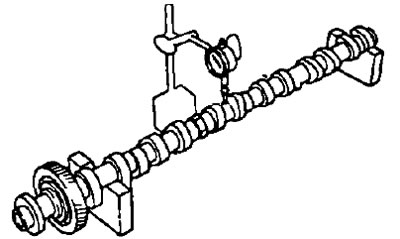
A. Check the camshaft for bent.
- A) Lay the camshaft on the prisms.
- b) Use a dial gauge to check the camshaft runout relative to the middle journal.
- Max Runout:
- 3S-FE, 4S-FE, 4A-FE and 5E-FE, 7A-FE - 0.04mm
- 2C, 2C-T, 3S-GE - 0.06 mm
If the runout exceeds the allowable value, replace the camshaft.
B. Check the height of the camshaft cams by measuring it with a micrometer.
- 2C:
- Nominal jaw height:
- intake - 47.90 mm
- graduation - 48.35 mm
- Minimum admissible height of cams:
- intake - 47.40 mm
- graduation - 47.85 mm
- Nominal jaw height:
- 2C-T:
- Nominal jaw height:
- intake - 47.35-47.45 mm
- graduation - 48.30-48.40 mm
- Minimum admissible height of cams:
- intake - 46.90 mm
- graduation - 47.85 mm
- Nominal jaw height:
- 3S-FE:
- Inlet camshaft lobe height:
- nominal - 42.51-42.61 mm
- minimum allowable - 42.40 mm
- Exhaust camshaft lobe height:
- nominal - 40.36-40.46 mm
- minimum allowable - 40.25 mm
- Inlet camshaft lobe height:
- 3S-GE:
- Nominal jaw height - 41.31-41.41 mm
- The minimum allowable jaw height is 41.20 mm
- 4S-FE:
- Inlet camshaft lobe height:
- nominal - 34.91-35.01 mm
- minimum allowable - 34.76 mm
- Exhaust camshaft lobe height:
- nominal - 40.36-40.46 mm
- minimum allowable - 40.25 mm
- Inlet camshaft lobe height:
- 4A-FE, 7A-FE:
- Inlet camshaft lobe height:
- nominal - 34.81-34.91 mm
- minimum allowable - 35.41 mm
- Exhaust camshaft lobe height:
- nominal - 41.96-42.06 mm
- minimum allowable - 41.55 mm
- Inlet camshaft lobe height:
- 5E-FE:
- Inlet camshaft lobe height:
- nominal - 41.51-41.61 mm
- minimum allowable - 41.36 mm
- Exhaust camshaft lobe height:
- nominal - 41.31-41.41 mm
- minimum allowable - 41.16 mm
- Inlet camshaft lobe height:
If cam height is less than minimum, replace camshaft.
B. Check the dimensions of the camshaft bearing journals by measuring their diameters with a micrometer.
Diameter of bearing journals of camshafts:
- 3S-GE, 3S-FE 4S-FE - 26.959-26.975 mm
- 4A-FE, 7A-FE, 5E-FE
- 1st support - 24.949-24.965 mm
- the rest - 22.949-22.965 mm
- 2C, 2C-T - 27.979-27.995 mm
If the journal diameters are outside the specifications, check the oil clearance between the journal and the bearing.
D. Check the condition of the camshaft bearings for chipping and scratches on their surfaces. In the presence of the listed defects replace covers of bearings or a head of the block of cylinders in gathering.
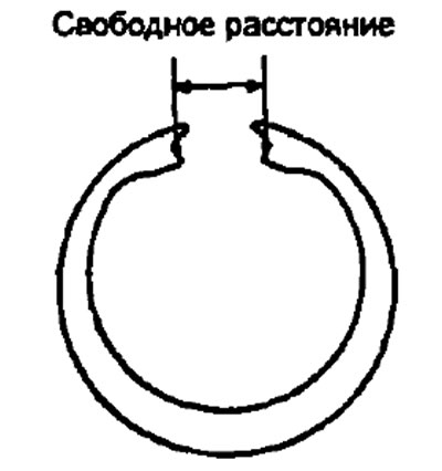
D. (3S-FE, 4S-FE, 3S-GE, 4A-FE.5E-FE, 7A-FE) Check the condition of the leaf split spring of the camshaft gear by measuring the clearance of its lock in the free state.
Free clearance:
- S and E series engines - 22.5-22.9 mm
- A series engines - 17.0-17.6 mm
If the lock free play is out of specification, replace the pinion leaf spring.
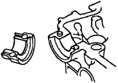
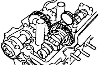
E. Check the radial oil clearance in the camshaft bearings.
- A) Clean the working surfaces of the camshaft journals and bearing caps.
- b) Lay the camshafts in the bed of the cylinder head.
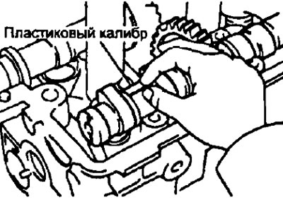
- V) Place a piece of plastic gauge on each camshaft journal.
Note:
- (4A-FE, 1A-FE) The arrows on the bearing caps must point towards the front of the engine.
- (2S, 2S-T) tighten the bolts in three steps, starting from the inside.
- G) Install bearing caps. Tighten the cover bolts.
- Torque:
- engines of the S, C series - 18 Nm
- engines series A, E - 13 Nm
Note: Do not rotate the camshaft.
- d) Remove bearing caps.
- e) Measure the width of the flattened plastic gauges at their widest point and calculate the gap.
- Radial clearance in camshaft bearings:
- Nominal:
- A and E series engines - 0.035-0.072 mm
- C series engines - 0.037-0.073 mm
- S series motors - 0.025-0.062 mm
- Maximum allowable - 0.1 mm
- Nominal:
If the clearance is greater than the maximum, replace the camshaft. Replace bearing caps and cylinder head if necessary.
- and) Remove any remaining plastic gauges.
G. Check the camshaft end play.
- A) Install the camshaft in the bed of the cylinder head.
- b) Use an indicator to measure the end play while moving the camshafts back and forth.
Axial clearance of camshafts:
- 2C, 2C-T:
- nominal - 0.080-0.18 mm
- maximum allowable - 0.25 mm
- 3S-FE, 4S-FE:
- Nominal:
- intake valves - 0.045-0.100 mm
- exhaust valves - 0.030-0.085 mm
- Maximum allowable:
- intake valves - 0.12 mm
- exhaust valves - 0.10 mm
- Nominal:
- 3S-GE:
- nominal - 0.025-0.062 mm
- maximum allowable - 0.08 mm
- 4A-FE, 7A-FE:
- Nominal:
- intake valves - 0.030-0.085 mm
- exhaust valves - 0.035-0.090 mm
- Maximum allowable - 0.11 mm
- Nominal:
- 5E-FE:
- Nominal - 0.045-0.100 mm
- Maximum allowable - 0.12 mm
If the axial clearance is greater than the maximum allowable, replace the camshaft. If necessary, replace bearing caps and cylinder head.
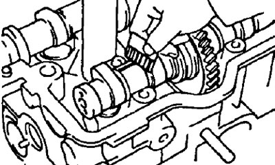
3. (3S-FE, 4S-FE, 4A-FE, 5E-FE and 7A-FE) Measure the backlash in the gearing of the camshafts.
- A) Install both camshafts in the head of the block without installing the exhaust camshaft auxiliary gear.
- b) Use a dial indicator to measure the backlash in the gearing.
- Nominal clearance - 0.02-0.20 mm
- Maximum clearance - 0.30 mm
If the clearance is greater than maximum, replace the camshafts.
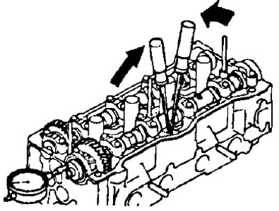
11. Check up pushers and borings under pushers in the case of a head of the block.
- A) Using an indicator-bore gauge, measure the diameters of the bores for the pushers in the cylinder head.
- Boring diameter for the pusher in the block head:
- 2C, 2C-T - 37.960-37.975 mm
- 3S-FE - 31.000-31.018 mm
- 4S-FE - 28.000-28.021 mm
- 3S-GE, 5E-FE - 28.000-28.021 mm
- 4A-FE, 7A-FE - 31.000-31.025 mm
- b) Measure the diameter of the pusher with a micrometer.
- Pusher diameter:
- 2C, 2C-T - 37.922-37.932 mm
- 3S-FE, 4A-FE, 7A-FE - 30.966-30.976 mm
- 3S-GE, 4S-FE, 5E-FE - 27.975-27.985 mm
- V) Check oil clearance. Subtract the tappet diameter from the tappet bore in the head housing and determine the clearance.
- Gap between the pusher and the wall of the bore for the pusher: Nominal:
- 4A-FE, 7A-FE - 0.024-0.059 mm
- 2G, 2C-T - 0.028-0.053 MM
- 3S-GE, 3S-FE - 0.024-0.052 mm
- 4S-FE, 5E-FE - 0.015-0.046 mm
- 4A-FE, 7A-FE, 3S-GE3S-FE, 4S-FE - 0.07mm
- 2C, 2C-T, 5E-FE - 0.10 mm
If the gap exceeds the maximum allowable, replace the pusher. If necessary, replace the cylinder head.
12. (Except 4A-FE, 7A-FE)Using a precision straightedge and a flat feeler gauge, check the contact surfaces of the manifolds for non-flatness of the mating surfaces.
Maximum non-flatness:
- 2S, 2S-G - 0.40 mm
- 3S-FE, 4S-FE - 0.30 mm
- 3S-GE - 0.20 mm
- 5E-FE - 0.05 mm
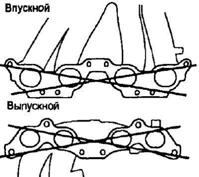
3S-FE, 4S-FE, 3S-GE
13. (5E-FE) If necessary, replace the spark plug tube gaskets.
- A) Using a screwdriver, remove the gasket.
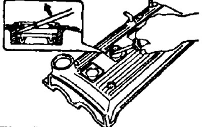
- b) Press the spark plug tubes flush with the cylinder head cover.
- V) Apply some sealant to the gasket tabs.