Note:
- Thoroughly clean all parts to be assembled.
- Before assembly, lubricate with fresh engine oil all the parts that form the nodes of rotation or sliding.
- Replace all gaskets, O-rings and seals with new ones.
1. Install the main bearing shells.
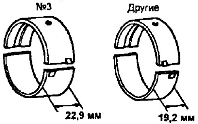
Note: Main bearing shells vary in width: 19.2mm and 22.9mm (3S-FE, 4S-FE) and 23.0 mm (3S-GE). Earbuds 22.9 mm wide (23.0 mm) correspond to the Ne3 main journal, and the 19.2 mm wide liners correspond to the rest of the main journals. The upper shells of the main bearings have an oil channel and oil holes.
3S-FE, 4S-FE | 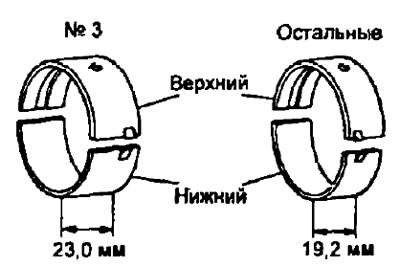
3S-GE |
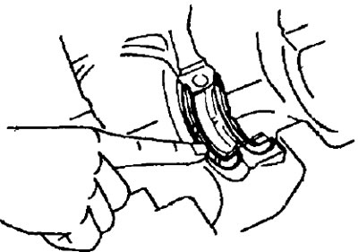
- A) Align the tabs of the upper bearing shells with the grooves (grooves) bed of the cylinder block and insert the liners.
- b) Align the tabs of the lower bearing shells with the grooves (grooves) in the main bearing caps and install them.
Note: Each main bearing cap is numbered.
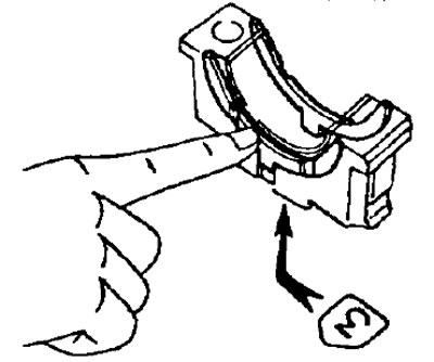
2. Install the upper thrust washers in the #3 main bearing block bed, with the grease canes facing out.
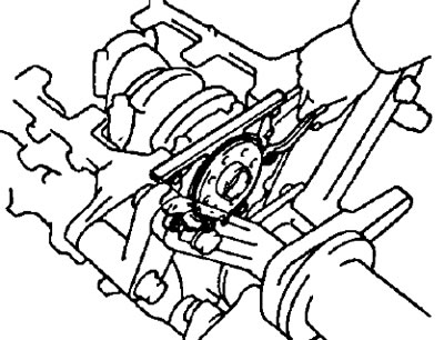
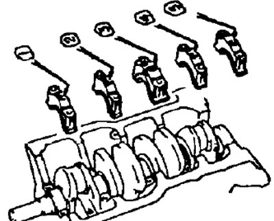
3. Lay a cranked shaft in the block of cylinders.
4. Establish covers of radical bearings and persistent half rings.
- A) Install the two thrust washers on the #3 bearing cap with the oil grooves facing outward.
- b) Install five main bearing caps.
Note: each bearing cap has a number and a label "before".
- V) Apply a light coat of engine oil to the threads and under the heads of the main bearing cap bolts.
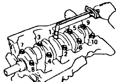
- G) Install and evenly tighten the main bearing cap bolts in several passes in the sequence shown in the illustration.
- Torque:
- 2C, 2C-T - 103 Nm
- 3S-FE, 4S-FE, 3S-GE, 4A-FE, 7A-FE and 5E-FE - 58 Nm
- d) After screwing in the bolt and using a torque wrench, check that the crankshaft turning force is less than 20 Nm and that the shaft rotates evenly.
- e) Using a dial gauge, measure the crankshaft axial clearance while moving the crankshaft with a screwdriver.
If the axial clearance is greater than the maximum, replace the thrust washers
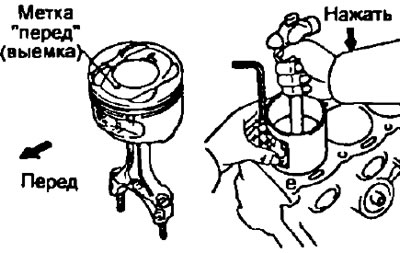
5. Install the piston and connecting rod assembly.
- A) Put pieces of hose on the threaded parts of the connecting rod bolts to prevent damage to the crankshaft journals.
- b) Using a ring compressor, install the piston kits into the cylinders according to their numbers, orienting the marks "before" on the pistons towards the front of the engine as shown.
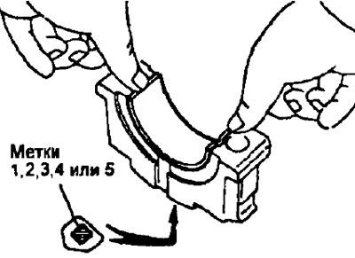
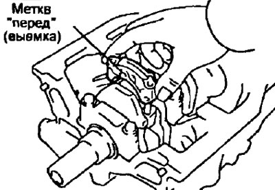
6. Establish the bottom covers of rods.
A. Install the lower connecting rod caps to the connecting rods.
- A) Check that the numbering of the connecting rod bearing caps and connecting rods match.
- b) Install the connecting rod caps so that the marks "before" were facing the front of the engine.
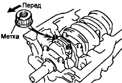
B. Install nuts on connecting rod bolts (or tighten bolts 7A-FE).
Note:
- The nuts are tightened in two steps.
- If any of the connecting rod bolts is broken or deformed, replace it.
- A) Apply a light coat of engine oil to the bolt threads, under the connecting rod cap nuts, or under the bolt heads (7A-FE).
- b) Carry out the initial tightening of the nuts (bolts 7A-FE) connecting rod caps evenly in several passes.
- Torque:
- 2C, 2C-T, 3S-GE - 66 Nm
- 3S-FE, 4S-FE, 7A-FE - 25 Nm
- 4A-FE - 29 Nm
- 5E-FE - 39 Nm
If any nut (bolt 7A-FE) not tightened to the specified torque, replace the bolt and nut.
(3S-FE, 4S-FE, 4A-FE and 7A-FE)
- V) Mark bolts and nuts with paint, (or bolt head 7A-FE), as shown in the pictures.
- G) Tighten the nuts (bolts 7A-FE) 90°as shown in the illustrations.
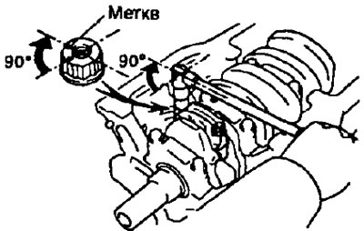
- d) Make sure the marks on the nuts are now 90°from the mark on the connecting rod bolts (or the marks on the bolt heads are rotated 900 from original position 7A-FE).
(All engines)
- V) Check that the crankshaft rotates evenly and that the cranking force is no more than 120 Nm.
- and) Using a dial indicator, measure the end play while moving the connecting rod back and forth.
If the end play is greater than the maximum, replace the connecting rod assembly. If necessary, replace the crankshaft.
7. Install new gasket and rear oil seal retainer by tightening six bolts, or four bolts (5E-FE).
- Torque:
- 5E-FE - 7 Nm
- the rest - 13 Nm