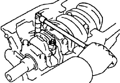
2. (2C, 2C-T, 3S-FE) Remove oil nozzles.
3. Check the value of the axial clearance of the connecting rod bearing with a clock indicator, moving the connecting rod back and forth along the connecting rod journal of the crankshaft.
- Standard axial clearance:
- A series engines - 0.15-0.250 mm
- C series engines - 0.08-0.300 mm
- S series motors - 0.16-0.312 mm
- E series engines - 0.15-0.350 mm
- Maximum axial clearance:
- A series engines - 0.30 mm
- C series engines - 0.40 mm
- S series motors - 0.35 mm
- E series engines - 0.45 mm
If the end play is greater than the maximum, replace the connecting rod assembly. Replace crankshaft if necessary.
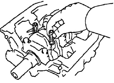
4. Remove the connecting rod cap and check the radial clearance of the connecting rod bearing.
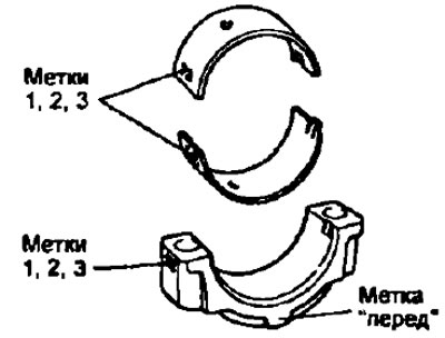
- A) Check alignment of marks on connecting rod and connecting rod cap to ensure correct reassembly.
If there are no marks, apply them to the caps and connecting rods with a core.
- b) Remove two nuts (bolts 7A-FE) fixing the bottom cover of the connecting rod.
- V) Lightly tap the connecting rod bolts with a plastic-headed hammer to release the lower connecting rod cap.
Note: The bottom half of the bushing must remain in the connecting rod cap.
- G) Put pieces of hose on the protruding ends of the bolts to prevent damage to the surface of the connecting rod journal.
- d) Clean the crankpin and bearings.
- e) Check the connecting rod journal and bearing surfaces for pitting and scratches. If there are scratches or scratches, replace the bearings. Regrind journals or replace crankshaft if necessary.
Note: Do not confuse the upper and lower bearing shells.
- and) Install a plastic gauge to measure the clearances in the plain bearings across the crankpin.
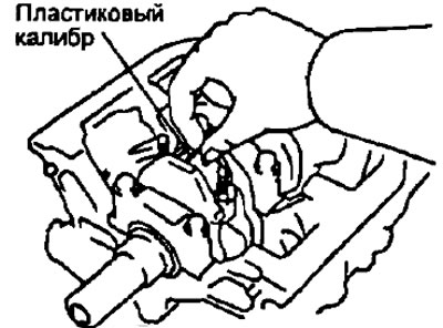
- h) Install the connecting rod lower cover by aligning the match marks.
- Torque:
- 3S-FE, 4S-FE, 4A-FE and 7A-FE
- 1st stage - 27 Nm
- 2nd stage - rotate 900
- 2C, 2C-T, 3S-GE - 66 Nm
- 5E-FE - 39 Nm
- 3S-FE, 4S-FE, 4A-FE and 7A-FE
Note:
- Do not rotate the crankshaft.
- Apply some oil to the threads of the bolts and under the nuts (for bolt heads 7A-FE) before installing them.
- And) Remove the bottom cover of the connecting rod by unscrewing the nuts (bolts 7A-FE).
- To) Measure the maximum width of the flattened gauge wire, using it to determine the size of the connecting rod bearing gap.
Conrod bearing clearance:
- Engine 2C:
- nominal - 0.044-0.072 mm
- repair (0,25) - 0.035-0.081 mm
- maximum - 0.10 mm
- Engine 2S-T:
- nominal - 0.042-0.066 mm
- repair (0,25) - 0.043-0.089 mm
- maximum - 0.10 mm
- Engines 3S-FE, 4S-FE, 3S-GE:
- nominal - 0.024-0.055 mm
- repair (0,25) - 0.023-0.069 mm
- maximum - 0.08 mm
- Engines 4A-FE, 7A-FE:
- nominal - 0.020-0.051 mm
- repair (0,25) - 0.019-0.065 mm
- maximum - 0.08 mm
- Engine 5E,FE:
- nominal - 0.016-0.048 mm
- repair (0,25) - 0.015-0.058 mm
- maximum - 0.08 mm
If the clearance is greater than the maximum, replace the bearings. Regrind or replace crankshaft if necessary.
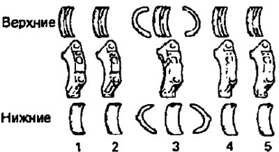
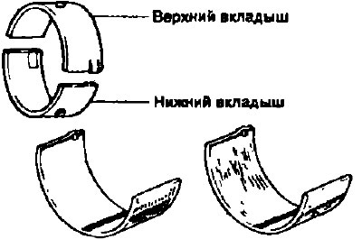
Note: when replacing bearings of nominal size, it is necessary to use bearings of the same size group indicated on the bearing cap.
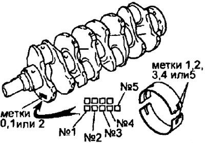
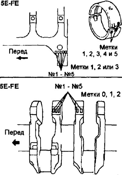
There are size groups of liners, designated "1", "2", "3" for engines 2C, 3S-FE, 4S-FE, 3S-GE, 4A-FE, 5E-FE, 7A-FE and "2", "3", "4", "5", respectively for the 2S-T engine.
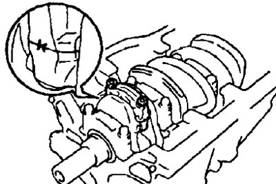
At the same time, the protrusion (label «before») on the connecting rod cap must point towards the front of the engine (in the direction opposite to the power take-off).
The nominal dimensions of the liners according to their thickness:
- Engines 4A-FE, 7A-FE:
- label "1" - 1.486-1.490 mm
- label "2" - 1,490-1,494 mm
- label "3" - 1.494-1.498 mm
- repair (0,25) - 1.607-1.613 mm
- Engines 2C, 2C-T:
- label "1" - 1.474-1.478 mm
- label "2" - 1.478-1.482 mm
- label "3" - 1.482 - 1.485 mm
- only 2C-T:
- label "4" - 1.485-1.489 mm
- label "5" - 1.489-1.493 mm
- Engines 3S-FE, 3S-GE, 4S-FE:
- label "1" - 1.484-1.488 mm
- label "2" - 1.488-1.492 mm
- label "3" - 1.492-1.496 mm
- Engine 5E-FE:
- label "1" - 1.487-1.491 mm
- label "2" - 1.491-1.495 mm
- label "3" - 1.495-1.499 mm
- repair (0,25) - 1.609-1.615 mm
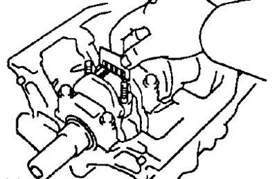
- l) Remove the remnants of the calibration wire from the working surfaces of the neck and liner.
5. Remove piston and connecting rod as an assembly.
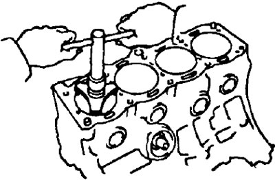
- A) Use a reamer to remove carbon deposits from the top of the cylinder as shown in the figure.
- b) Cover the connecting rod bolts with pieces of hose to protect the crankshaft from damage
- V) Remove the piston assembly with connecting rod and upper bearing shell through the top of the cylinder block.
Note:
- Keep bearings, connecting rod and cap together.
- Arrange the pistons with connecting rods and liners in a certain order
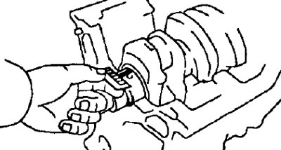
6. Using an indicator, measure the axial clearance of the crankshaft by moving the latter "back forward" with a screwdriver.
Standard axial clearance:
- 3S-FE, 4S-FE, 3S-GE, 4A-FE, 7A-FE - 0.020-0.022 mm
- 2C, 2C-T - 0.040-0.240 mm
- 5E-FE - 0.020-0.200 mm
- Maximum axial clearance - 0.3 mm
If the axial clearance is greater than the maximum allowable, replace the thrust washers.
Thickness of thrust half rings:
- 3S-FE, 4S-FE, 3S-GE 4A-FE, 7A-FE - 2.440-2.490 mm
- 2C, 2C-T:
- nominal - 2,680-2,730 mm
- repair (0,125) - 2.743-2.793 mm
- repair (0,250) - 2.805-2.855 mm
- 5E-FE:
- nominal - 2.430-2.480 mm
- repair (0.125) - 2.493-2.543 mm
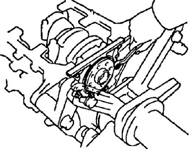
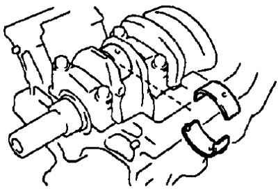
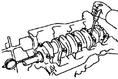
7. Remove the main bearing caps and check the radial oil clearances.
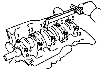
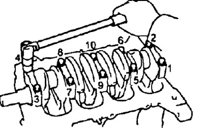
- A) Evenly loosen and remove the main bearing cap bolts in several passes as shown.
- b) Swinging the unscrewed bolts in the holes of the main bearing caps, separate and remove the caps together with the lower shells and lower thrust half rings (the latter are installed only in the main bearing area No. 3).
Note:
- Keep the main bearing caps together with the lower bearings.
- Position the main bearing caps and thrust washers in the correct order.
- V) Raise the crankshaft.
Note: Leave the upper bearing shells and upper thrust washers in the cylinder block.
- G) Clean each main journal and bearings.
- d) Check the surface of each main journal and bearings for pitting and scratches.
- If the neck or insert is damaged, replace the inserts. Regrind or replace crankshaft if necessary.
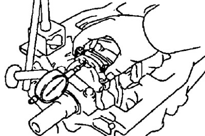
- e) Lay a cranked shaft in the block of cylinders.
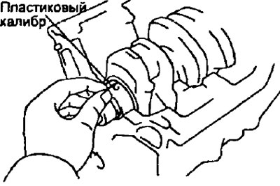
- and) Place a plastic bearing clearance gauge on each journal.
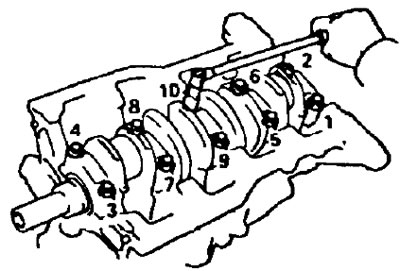
- h) Establish covers of radical bearings and tighten bolts in the sequence shown in drawing.
- Torque:
- 3S-FE, 4S-FE, 3S-GE, 4A-FE, 7A-FE - 59 Nm
- 2C, 2C-T - 103 Nm
- 5E-FE - 57 Nm
Note: Do not rotate the crankshaft.
- And) Remove the main bearing caps with lower shells and thrust washers (the latter are installed only in the main bearing area No. 3).
- To) Measure the maximum width of the flattened gauge wire to determine the radial oil clearance.
Main bearing clearance:
- 4A-FE, 7A-FE:
- nominal - 0.015-0.033 mm
- repair (0,25) - 0.016-0.056 mm
- maximum - 0.100 mm
- 2C, 2C-T:
- nominal - 0.032-0.056 mm
- repair (0,25) - 0.033-0.079 mm
- maximum - 0.100 mm
- 3S-FE, 3S-GE, 4S-FE:
- bearing #3
- standard - 0.025-0.044 mm
- repair (0,25)
- 3S-FE, 4S-FE - 0.027-0.067 mm
- 3S-GE - 0.021-0.610 mm
- rest
- standard - 0.015-0.034 mm
- repair (0,25)
- 3S-FE, 4S-FE - 0.019-0.059 mm
- 3S-GE - 0.029-0.690 mm
- maximum gap: 0.080mm
- bearing #3
- 5E-FE:
- nominal - 0.016-0.049 mm
- repair (0,25) - 0.015-0.055 mm
- maximum - 0.080 mm
Note: when replacing the cylinder block assembly, the standard bearing clearance will accordingly be:
- A series engines - 0.015-0.045 mm
- S-series engines:
- bearing No. 3 - 0.027-0.054 mm
- the rest - 0.017-0.044 mm
- E series engines - 0.018-0.045 mm
If the oil clearance is greater than the maximum, replace the bearings.
Regrind or replace crankshaft if necessary.
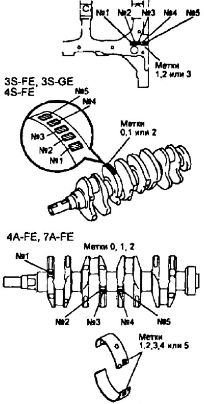
Note: When replacing nominal size inserts, inserts of the same size group must be used. If the bearing size group number cannot be determined, select the correct bearing from the table by adding the cylinder block size group number to the crankshaft size group number. There are five standard earbud size groups marked '1", "2"', "3", "4" And "5" respectively.
2S, 2S-T
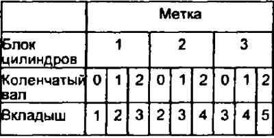
Example: Label "2" on the cylinder block + mark "1" on crankshaft = sum "3" (required insert #3).
Diameter of the bed of the main bearing of the cylinder block:
- Engines 4A-FE, 7A-FE:
- label "1" - 52.025-52.031 mm
- label "2" - 52.031-52.037 mm
- label "3" - 52.037-52.043 mm
- Engines 2C, 2C-T:
- label "1" - 61.000-61.008 mm
- label "2" - 61.008-61.016 mm
- label "3" - 61.016-61.024 mm
- Engines 3S-FE, 3S-GE, 4S-FE:
- label "1" - 59.020-59.026 mm
- label "2" - 59.026-59.032 mm
- label "3" - 59.032-59.038 mm
- Engine 5E-FE:
- label "1" - 54.018-54.024 mm
- label "2" - 54.025-54.030 mm
- label "3" - 54.031-54.036 mm
Crankshaft journal diameter:
- Engines 4A-FE, 7A-FE:
- label "0" - 47.994-48.000 mm
- label "1" - 47.988-47.994 mm
- label "2" - 47.982-47.988 mm
- Engines 2C, 2C-T:
- label "0" — 56.994-57.000 mm
- label "1" - 56.983-56.994 mm
- label "2" - 56.982-56.988 mm
- Engines 3S-FE, 3S-GE, 4S-FE:
- Label "0" 54.998-55.003 mm
- label "1" 54.993-54.998 mm
- label "2" 54.988-54.993 mm
- Engine 5E-FE:
- label "0" - 49.996-50.000 mm
- label "1" - 49.991-49.995 mm
- label "2" - 49.985-49.990 mm
Liner wall thickness (in the central part):
- Engines 4A-FE, 7A-FE:
- label "1" - 2.002-2.005 mm
- label "2" - 2.005-2.008 mm
- label "3" - 2.008-2.011 mm
- label "4" - 2.011-2.014 mm
- label "5" - 2.014-2.017 mm
- Engines 2C, 2C-T:
- label "1" - 1.979-1.983 mm
- label "2" - 1.983-1.987 mm
- label "3" - 1.987-1.990 mm
- label "4" - 1.990-1.994 mm
- label "5" - 1.994-1.998 mm
- Engines 3S-FE, 3S-GE, 4S-FE.
- Insert #3
- label "1" - 1.992-1.995 mm
- label "2" - 1.995-1.998 mm
- label "3" - 1.998-2.001 mm
- label "4" - 2.001-2.004 mm
- label "5" - 2.004-2.007 mm
- Rest
- label "1" - 1,997-2,000 mm
- label "2" - 2.000-2.003 mm
- label "3" - 2.003-2.006 mm
- label "4" - 2.006-2.009 mm
- label "5" - 2.009-2.012 mm
- Insert #3
- Engine 5E-FE:
- label "1" - 1,997-2,000 mm
- label "2" - 2.001-2.003 mm
- label "3" - 2.004-2.006 mm
- label "4" - 2.007-2.009 mm
- label "5" - 2.010-2.012 mm
- Example: Label "2" on the cylinder block + mark "1" on crankshaft = sum "3" (required insert #3).
Diameter of the bed of the main bearing of the cylinder block:
- Engines 4A-FE, 7A-FE:
- label "1" - 52.025-52.031 mm
- label "2" - 52.031-52.037 mm
- label "3" - 52.037-52.043 mm
- Engines 2C, 2C-T:
- label "1" - 61.000-61.008 mm
- label "2" - 61.008-61.016 mm
- label "3" - 61.016-61.024 mm
- Engines 3S-FE, 3S-GE, 4S-FE:
- label "1" - 59.020-59.026 mm
- label "2" - 59.026-59.032 mm
- label "3" - 59.032-59.038 mm
- Engine 5E-FE:
- label "1" - 54.018-54.024 mm
- label "2" - 54.025-54.030 mm
- label "3" - 54.031-54.036 mm
Crankshaft journal diameter:
- Engines 4A-FE, 7A-FE:
- label "0" - 47.994-48.000 mm
- label "1" - 47.988-47.994 mm
- label "2" - 47.982-47.988 mm
- Engines 2C, 2C-T:
- label "0" — 56.994-57.000 mm
- label "1" - 56.983-56.994 mm
- label "2" - 56.982-56.988 mm
- Engines 3S-FE, 3S-GE, 4S-FE:
- Label "0" - 54.998-55.003 mm
- label "1" - 54.993-54.998 mm
- label "2" - 54.988-54.993 mm
- Engine 5E-FE:
- label "0" - 49.996-50.000 mm
- label "1" - 49.991-49.995 mm
- label "2" - 49.985-49.990 mm
Liner wall thickness (in the central part):
- Engines 4A-FE, 7A-FE:
- label "1" - 2.002-2.005 mm
- label "2" - 2.005-2.008 mm
- label "3" - 2.008-2.011 mm
- label "4" - 2.011-2.014 mm
- label "5" - 2.014-2.017 mm
- Engines 2C, 2C-T:
- label "1" - 1.979-1.983 mm
- label "2" - 1.983-1.987 mm
- label "3" - 1.987-1.990 mm
- label "4" - 1.990-1.994 mm
- label "5" - 1.994-1.998 mm
- l) Remove the plastic gauges.
8. Remove the crankshaft.
- A) Raise the crankshaft.
- b) Remove the upper main bearing shells and upper thrust washers from the cylinder block.
Note: Place the main bearings and thrust washers in the specified order.