
A) Turning the crankshaft, sequentially set the pistons to TDC. Use a scraper to clean the surfaces of the piston bottoms from carbon deposits.
b) Using a scraper, remove the remnants of the head gasket from the surface of the cylinder block connector.
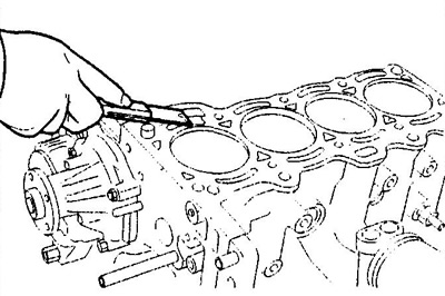
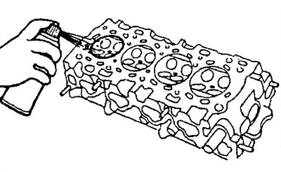
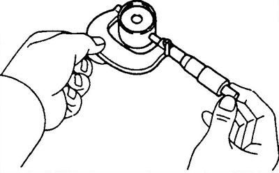
V) Use compressed air to remove carbon deposits and gasket residue from the surface of the cylinder block and bolt holes.
Note: When using compressed air, take care of your eyes.
2. Clean the cylinder head.
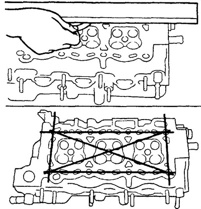
A) Clean the surface of the head of the block from the remnants of the head gasket.
Note: Be careful not to damage the gasket mating surface of the block head.
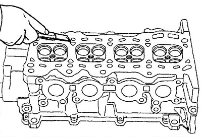
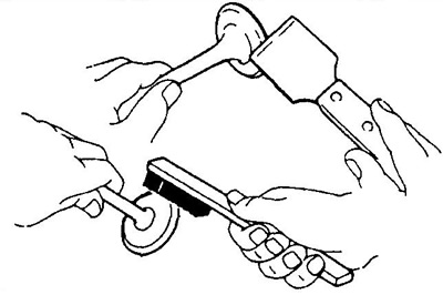
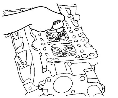
b) Clean the surfaces of the combustion chambers of the block head with a wire brush, removing any remaining carbon deposits.
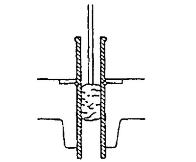
V) Clean the valve guide bores with a brush and solvent.
3. Check the cylinder head.
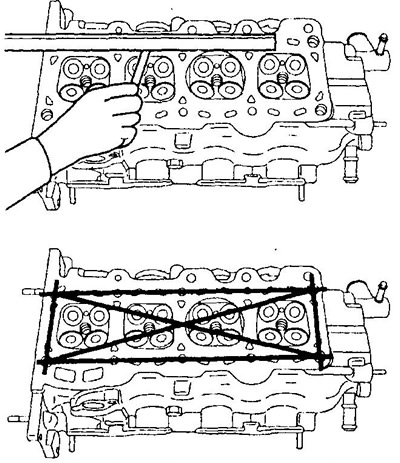
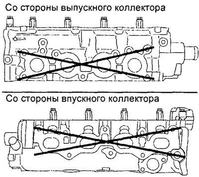
A) With a precision ruler and a flat feeler gauge, as shown in the figure, check the flatness of the working surfaces of the cylinder head mating:
- with the surface of the cylinder block;
- surfaces of the intake and exhaust manifolds.
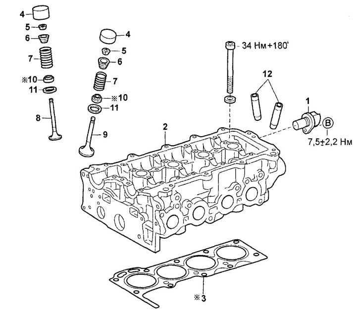
Dismantling and assembly of a head of the block of cylinders (K3 series).
1 - crankshaft position sensor,
2 - cylinder head,
3 - cylinder head gasket,
4 - valve lifter,
5 - crackers,
6 - valve spring plate,
7 - valve spring,
8 - inlet valve,
9 - exhaust valve,
10 - oil scraper cap,
11 - valve spring seat,
12 - valve guide.
KZ series.
EJ series.
Maximum allowable surface non-flatness:
KZ series:
- gas joint - 0.04 mm
- mating intake manifold - 0.10 mm
- mating exhaust manifold - 0.05 mm
EJ Series:
- gas joint - 0.10 mm
- mating intake manifold - 0.10 mm
- mating exhaust manifold - 0.10 mm
If the amount of flatness exceeds the maximum allowable, replace the cylinder head.
b) Using a penetrating dye, check for cracks in the combustion chambers, inlet and outlet ports, and at the gas interface. If there are cracks, replace the cylinder head.
4. Clean the valves.
A) Use a scraper to remove carbon deposits from the valve disc.
b) Clean the valve completely with a soft brush.
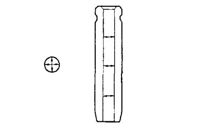
5. Check valve stem diameters and valve guide bores.
A) Measure the inside diameter of the valve guides with a bore gauge.
Guide bush inner diameter:
- K3 series - 5.010 - 5.022 mm
- EJ series - 5.000 - 5.012 mm
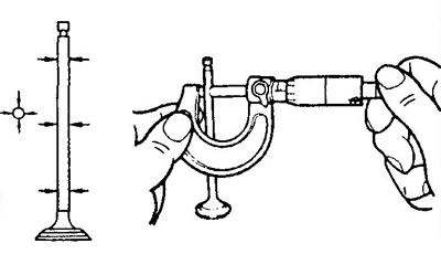
b) Measure the diameter of the valve stem with a micrometer.
Valve stem diameter:
- intake valve - 4.975- 4.990 mm
- exhaust valve - 4.965 - 4.980 mm
V) Find the gap between the valve stem and guide by measuring the difference between the valve stem diameter and the inner diameter of the valve guide.
Rated oil clearance:
KZ series:
- intake valve - 0.020 - 0.047 mm
- exhaust valve - 0.030 - 0.057 mm
EJ Series:
- intake valve - 0.020 - 0.060 mm
- exhaust valve - 0.030 - 0.070 mm
Max oil clearance:
KZ series:
- intake valve - 0.06 mm
- exhaust valve - 0.07 mm
EJ Series:
- intake valve - 0.07 mm
- exhaust valve - 0.08 mm
If the clearance is greater than the maximum, replace the valve and guide bushing.
6. If necessary, replace the valve guides.
A) Gradually heat the cylinder head in a water bath to a temperature of 80-100°C.
b) Using a drift and hammer, press out the guide bushing.
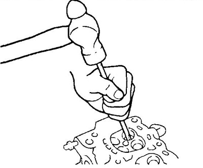
V) Install the valve guide. Using a drift and hammer, install the new valve guide so it protrudes from the cylinder head at:
KZ series - 14.5±0.3 mm
EJ Series:
- intake valve - 13.5±0.3 mm
- exhaust valve - 10.5±0.3 mm
e) Using a reamer, ream the inside hole of the guide to provide the correct clearance between the guide and valve stem.
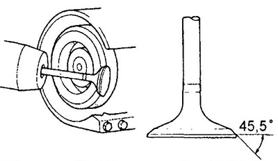
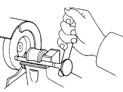
7. Check and lap the valves.
A) Grind the valves until traces of soot and scratches are eliminated.
b) Ensure that the lapped bevel of the valve forms an angle of 44.5°with respect to a plane perpendicular to the axis of the stem.
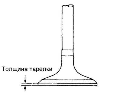
V) Check valve disc thickness.
- Nominal valve disc thickness - 1.0±0.2 mm
- The minimum thickness of the valve disc is 0.75 mm
If the thickness of the plate of the cylindrical part is less than the minimum allowable value, replace the valve.
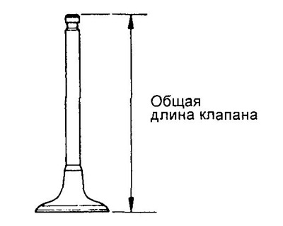
G) Check overall valve length.
Valve nominal length:
intake:
- KZ series - 88.15 mm
- EJ Series - 79.40mm
graduation:
- KZ series - 89.10 mm
- EJ Series - 79.80mm
If the overall length is less than the minimum, replace the valve.
d) Check the condition of the valve faces for wear.
If the valve face is worn, regrind the valve face or replace the valve.
Note: when regrinding, do not reduce the overall length of the valve below the minimum.
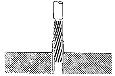
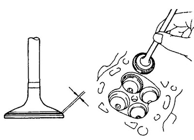
8. Check valve seats.
A) Use a 45°taper cutter to clean the valve seats.
b) Check for proper seating of the valve.
Apply a thin layer of white to the bevel of the valve. Press the valve face against the seat, but do not rotate the valve. Then remove the valve and inspect the valve seat and bevel.
If the paint remains around the entire circumference (360°) chamfers of the valve, the valve is concentric. Otherwise, replace the valve.
If the paint appears around the entire circumference (360°) valve seats, guide (sleeve) valves and valve seat are concentric. Otherwise, regrind the bevel.
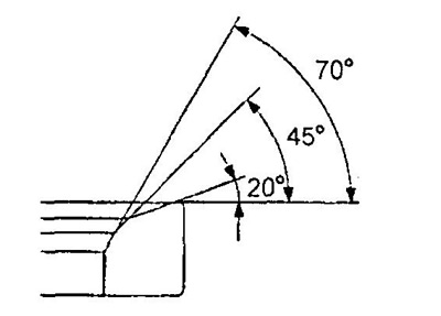
Make sure that the contact patch is in the middle of the valve face and has a width of 1.4 + 0.5 mm
Otherwise, adjust the chamfer as follows:
- If the contact patch is too high on the valve face, use 20°and 45°taper cutters to regrind the seat.
- If the contact patch is too low on the valve face, use 70°and 45°taper cutters to regrind the seat.
V) Hand lap the valve and valve seat using abrasive paste.
G) After lapping, clean the valve and valve seat.
9. Check the valve springs.
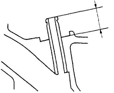
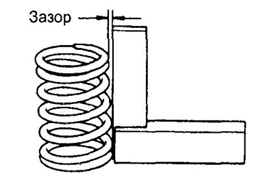
A) Using a metal square (90°), check that the valve spring is not perpendicular, as shown in the figure.
The maximum allowable non-perpendicularity is:
- KZ series - 1.8 mm
- EJ series - 1.6 mm
b) Using a caliper, measure the free length of the spring:
Valve Spring Length:
- KZ series - 45.54 mm
- EJ series - 36.97 mm
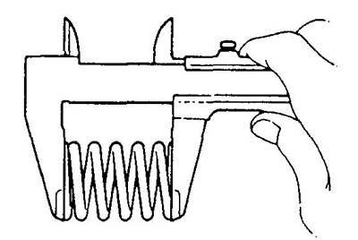
If the spring length is out of specification, replace the valve spring.
10. Check camshafts and bearings.
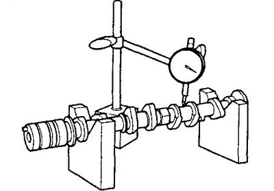
A. Check the camshaft end play.
A) Install the camshaft in the bed of the cylinder head.
b) Use an indicator to measure the axial clearance while moving the camshafts back and forth.
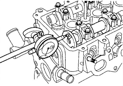
Axial clearance of camshafts:
KZ series:
- nominal - 0.10 - 0.24 mm
- maximum - 0.30 mm
EJ Series:
- nominal - 0.04 - 0.10 mm
- maximum - 0.15 mm
If the axial clearance is greater than the maximum, replace the camshaft. If necessary, replace bearing caps and cylinder head.
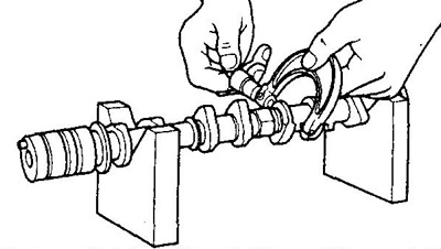
B. Check the camshaft runout.
Install the camshaft in V-shaped prisms and check its runout on the central neck.
- Maximum runout - 0.3 mm
B. Check the height of the camshaft lobes.
Inlet camshaft lobe height:
Rated:
- KZ series - 40.400 - 40.500 mm
- EJ-DE - 38.200 - 38.300 mm
- EJ-VE - 40.250 mm
Minimum:
- KZ series - 40.30 mm
- EJ-DE - 38.10 mm
Exhaust camshaft lobe height:
Rated:
- KZ series - 39.910 - 40.010 mm
- EJ-DE - 38.050 - 38.150 mm
- EJ-VE - 40.250 mm
Minimum:
- KZ series - 39.80 mm
- EJ-DE - 37.95mm
If the cam height is less than the minimum, replace the camshaft.
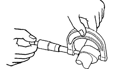
D. Check the dimensions of the camshaft bearing journals by measuring their diameters with a micrometer.
Diameter of bearing journals of camshafts:
KZ series:
1st reference:
- intake - 33.984 - 34.000 mm
- exhaust - 25.979 - 25.995 mm
- the rest - 22.979 - 22.995 mm
EJ Series:
- 1st support - 25.979- 25.995 mm
- the rest - 22.979- 22.995 mm
If the journal diameters are outside the specifications, check the radial clearance between the journal and the bearing.
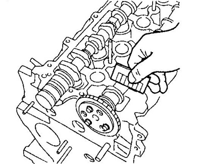
E. Check the radial clearance in the camshaft bearings.
A) Clean the working surfaces of the camshaft journals and bearing caps.
b) Lay the camshafts in the bed of the cylinder head.
V) Place a piece of plastic gauge on each camshaft journal.
G) Install bearing caps. Tighten the cover bolts (for more detailed procedures for installing camshafts, see subsection "Installation" section "cylinder head").
- Torque - 12.5±2.0 Nm
Note: Do not rotate the camshaft.
d) Remove bearing caps.
e) Measure the width of the flattened plastic gauges at their widest point and determine the gap.
Radial clearance in camshaft bearings:
EJ Series:
- nominal - 0.037 - 0.073 mm
- maximum - 0.10 mm
KZ series:
Inlet camshaft:
- neck No. 1 - 0.025 - 0.061 mm
- the rest - 0.037 - 0.073 mm
Exhaust camshaft - 0.037 - 0.073 mm
If the clearance is greater than the maximum, replace the camshaft. Replace bearing caps and cylinder head if necessary.
and) Remove any remaining plastic gauges.
11. Check up pushers and borings under pushers in the case of a head of the block.
A) Using an indicator-bore gauge, measure the diameters of the bores for the pushers in the cylinder head.
- Boring diameter for the pusher in the head of the block - 28.000 - 28.021 mm
b) Measure the diameter of the pusher with a micrometer.
- The nominal diameter of the pusher - 27.975-27.985
V) Check radial clearance.
Subtract the tappet diameter from the tappet bore in the head housing and determine the clearance.
- The gap between the pusher and the bore wall for the pusher is 0.015 - 0.046 mm
If the gap exceeds the maximum allowable, replace the pusher.