
- A) Use a scraper to remove carbon deposits and other carbon deposits from the piston crown.
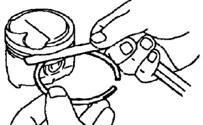
- b) Clean the piston grooves from deposits with a piece of a broken ring.
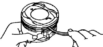
- V) Clean the plunger with solvent and a soft hair brush.
Note: Do not use a metal brush.
2. Check the piston and piston rings.
A. Check clearance between piston and cylinder.
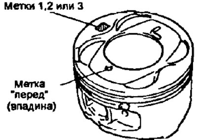
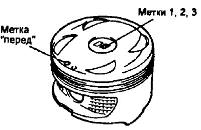
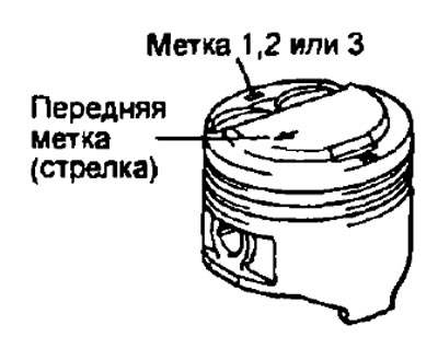
Note: there are three size groups of nominal piston diameters marked with marks (figures) "1", "2" And "3" respectively. The mark is applied to the piston head with an edge in the direction perpendicular to the axis of the piston pin or on the piston head in the center, (excavation) "before", along which the piston should be installed in the cylinder.
3S-FE, 4S-FE | 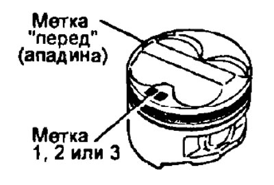
3S-GE |
4A-FE, 7A-FE | 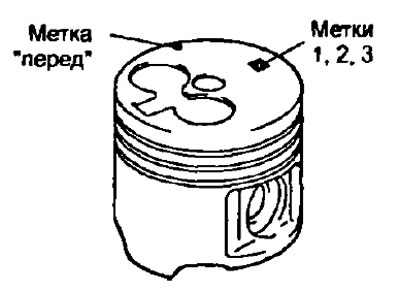
2C, 2C-T |
5E-FE
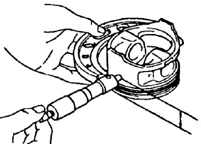
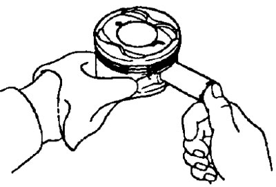
- A) Using a micrometer, measure the piston skirt diameter at a distance of 23 mm (5E-FE); 25 mm (3S-FE, 4S-FE, 4A-FE, 7A-FE); 30.1 mm (3S-GE); 32 mm (2S, 2S-T); (4S-FE - perpendicular to the axis of the finger) from the surface of the piston (below the level of the piston ring grooves) and in a direction perpendicular to the axis of the piston pin, as shown in the figure.
Nominal piston diameter:
- Engine 2C:
- label "1" - 85.945-85.955 mm
- label "2" - 85.955-85.965 mm
- label "3" - 85.965-85.975 mm
- repair (0,50) - 86.445-86.475 mm
- Engine 2S-T:
- label "1" - 85.878-85.888 mm
- label "2" - 85.888-85.898 mm
- label "3" - 85.898-85.908 mm
- repair (0,50) - 86.378-86.408 mm
- 3S-FE engine:
- label "1" - 85.865-85.875 mm
- label "2" - 85.875-85.885 mm
- label "3" - 85.885-85.895 mm
- repair (0,50) - 86.365-86.395 mm
- 3S-GE engine:
- label "1" - 85.960-85.970 mm
- label "2" - 85.970-85.980 mm
- label "3" - 85.980-85.990 mm
- Engine 4S-FE:
- nominal - 82.437-82.467 mm
- label "1" - 82.437-82.447 mm
- label "2" - 82.447-82.457 mm
- label "3" - 82.457-82.467 mm
- repair (0,50) - 82.937-82.967 mm
- repair (0,75) - 82.187-82.217 mm
- Engines 4A-FE, 7A-FE:
- label "1" - 80.905-80.915 mm
- label "2" - 80.915-80.925 mm
- label "3" - 80.925-80.935 mm
- repair (0,50) - 81.405-81.435 mm
- Engine 5E-FE:
- label "1" - 73.900-73.910 mm
- label "2" - 73.910-73.920 mm
- label "3" - 73.920-73.930 mm
- b) Measure the cylinder diameters in the direction of the engine axis.
- V) Find the difference between the measured piston diameter and cylinder diameter.
Clearance between cylinder and piston:
- 2C:
- nominal - 0.045-0.065 mm
- maximum - 0.15 mm
- 2G-T:
- nominal - 0.112-0.132 mm
- maximum - 0.182 mm
- 3S-FE:
- nominal - 0.125-0.145 mm
- maximum - 0.165 mm
- 3S-GE:
- nominal - 0.030-0.050 mm
- maximum - 0.070 mm
- 4S-FE:
- nominal - 0.053-0.073 mm
- maximum - 0.120 mm
- 4A-FE, 7A-FE:
- nominal - 0.085-0.105 mm
- maximum:
- 4A-FE - 0.130 mm
- 7A-FE - 0.200 mm
- 5E-FE:
- nominal - 0.09-0.11 mm
- maximum - 0.13 mm
If clearance is greater than maximum, replace all four pistons and bore all four cylinders. Replace the cylinder block if necessary.
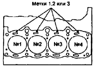
Note: When using a new cylinder block, use the piston with the same mark (number), which is the diameter of the cylinder. The cylinder diameter is marked on the cylinder block in the places shown in the figure.
B. Check end clearance "compression ring - piston groove", by measuring it with a flat feeler gauge as shown in the figure.
Rated Clearance:
- Compression ring #1:
- 2C - 0.100-0.140 mm
- 2S-T - 0.047-0.111 mm
- 3S-FE - 0.040-0.080 mm
- 4S-FE - 0.030-0.070 mm
- 3S-GE - 0.040-0.080 mm
- 4A-FE, 7A-PE - 0.045-0.085 mm
- 5E-FE - 0.040-0.080 mm
- Compression ring #2:
- 3S-FE, 4S-FE, 3S-GE, 4A-FE, 5E-FE, 7A-FE - 0.030-0.070 mm
- 2C, 2C-T - 0.050-0.090 mm
- Oil ring:
- 20, 2S-T - 0.030-0.070 mm
If the clearance is more than acceptable, replace the piston.
B. Check the clearance in the piston ring lock.
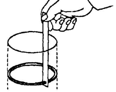
- A) Insert the piston ring into the cylinder.
- b) Use the piston to push the ring a distance of 110 mm (3S-FE, 5E-FE); 104 mm (7A-FE); 100 mm (3S-GE) ', 87 mm (4A-FE); from the surface of the cylinder block, as shown in the figure.
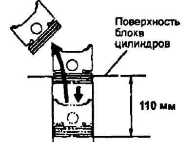
- V) Use a flat feeler gauge to measure the gap in the lock.
- Engine 2C:
- Rated Clearance:
- compression ring No. 1 - 0.27-0.54 mm
- compression ring No. 2 - 0.45-0.72 mm
- oil scraper ring (scrapers) - 0.10-0.82 mm
- Max Clearance:
- compression ring No. 1 - 1.34 mm
- compression ring No. 2 - 1.52 mm
- oil scraper ring (scrapers) - 1.62 mm
- Rated Clearance:
- Engine 2S-T:
- Rated Clearance:
- compression ring No. 1 - 0.27-0.49 mm
- compression ring No. 2 - 0.35-0.62 mm
- scraper ring (scrapers) - 0.20-0.52 mm
- Max Clearance:
- compression ring No. 1 - 1.29 mm
- compression ring No. 2 - 1.42 mm
- oil scraper ring (scrapers) - 1.32 mm
- Rated Clearance:
- 3S-FE engine:
- Rated Clearance:
- compression ring No. 1 - 0.27-0.50 mm
- compression ring No. 2 - 0.27-0.51 mm
- oil scraper ring (scrapers) — 0.20 - 0.550 mm
- Max Clearance:
- compression ring No. 1 - 1.10 mm
- compression ring No. 2 - 1.11 mm
- oil scraper ring (scrapers) - 1.15 mm
- Rated Clearance:
- 3S-GE engine:
- Rated Clearance:
- compression ring No. 1 - 0.33-0.55 mm
- compression ring No. 2 - 0.45-0.67 mm
- oil scraper ring (scrapers) - 0.20-0.60 mm
- Max Clearance:
- compression ring No. 1 - 0.85 mm
- compression ring No. 2 - 0.97 mm
- oil scraper ring (scrapers) - 0.90 mm
- Rated Clearance:
- Engine 4S-FE:
- Rated Clearance:
- compression ring No. 1 - 0.25-0.38 mm
- compression ring No. 2 - 0.20-0.32 mm
- scraper ring (scrapers) - 0.15-0.40 mm
- Max Clearance:
- compression ring No. 1 - 0.98 mm
- compression ring No. 2 - 0.92 mm
- oil scraper ring (scrapers) - 1.00 mm
- Rated Clearance:
- Engine 4A-FE:
- Rated Clearance:
- compression ring No. 1 - 0.25-0.45 mm
- compression ring No. 2 - 0.35-0.60 mm
- oil scraper ring (scrapers) - 0.10-0.50 mm
- Rated Clearance:
- Engine 7A-FE:
- Rated Clearance:
- compression ring No. 1 - 0.25-0.35 mm
- compression ring No. 2 - 0.35-0.50 mm
- oil scraper ring (scrapers) - 0.15-0.45 mm
- Rated Clearance:
- 4A-FE, 7A-FE:
- Max Clearance:
- compression ring No. 1 - 1.05 mm
- compression ring No. 2 - 1.20 mm
- oil scraper ring (scrapers) - 1.10 mm
- Max Clearance:
- Engine 5E-FE:
- Rated Clearance:
- compression ring No. 1 - 0.26-0.48 mm
- compression ring No. 2 - 0.300-0.570 mm
- oil scraper ring (scrapers) - 0.130-0.500 mm
- Max Clearance:
- compression ring No. 1 - 1.07 mm
- compression ring No. 2 - 1.02 mm
- oil scraper ring (scrapers) - 1.10 mm
- Rated Clearance:
If the gap in the lock is greater than the maximum, replace the piston ring. If the gap in the lock is greater than the maximum even with a new piston ring, bore all cylinders or replace the cylinder block.
D. Check piston pin.
When the piston is heated to 60°C, the piston papets should move in the piston without significant effort. After checking, remove the piston pin.
3. Check the concentricity of the connecting rod.
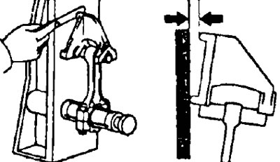
A. Using the special tool and a feeler gauge, check the bending of the connecting rod as shown in the illustration.
- Maximum allowable bend per 100 mm length:
- 5E-FE - 0.03 mm
- the rest - 0.05 mm
If twisting is more than acceptable, replace the connecting rod along with the connecting rod cap.
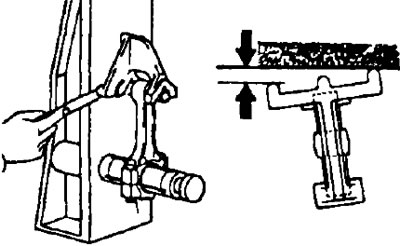
In the same way, check the twisting of the connecting rod, as shown in the figure.
- Maximum twist per 100 mm length:
- motors series A, E - 0.05 mm
- motors series C, S - 0.15 mm
B.(2C, 2C-T, 3S-FE. 4S-FE, 3S-GE) Check piston pin oil clearance.
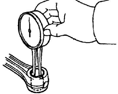
- A) Using a inside gauge, measure the inside diameter of the connecting rod bushing.
- Sleeve inner diameter:
- 2C, 2C-T - 27.011-27.023 mm
- 3S-FE, 3S-GE - 22.005-22.017mm
- 4S-FE:
- mark A - 20.004-20.007 mm
- mark B - 20.007-20.010 mm
- mark C - 20.010-20.013 mm
- mark D - 20.013-20.016 mm
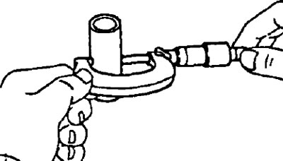
- b) Using a micrometer, measure the diameter of the piston pin.
- Piston pin diameter:
- 2C, 2C-T - 27.000-27.012 mm
- 3S-FE, 3S-GE - 21.997-22.009 mm
- 4S-FE:
- mark A - 20.013-20.016 mm
- mark B - 20.016-20.019 mm
- mark C - 20.019-20.022 mm
- mark D - 20.022-20.025 mm
- V) Subtract the measured piston pin diameter from the measured bushing inside diameter.
- Rated oil clearance:
- 2C, 2C-T - 0.007-0.015 mm
- 3S-FE, 3S-GE - 0.005-0.011 mm
- 4S-FE - 0.006-0.012 mm
- Maximum oil clearance - 0.05 mm
If the oil clearance is greater than the maximum, replace the sleeve If necessary, replace the piston and piston pin assembly
IN.(2C, 2C-T. 3S-FE, 4S-FE, 3S-GE)If necessary, replace the connecting rod bushing.
- A) Using a drift and a press, press the bushing out of the connecting rod head.
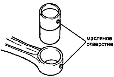
- b) (3S-FE, 4S-FE, 3S-GE) Align the lubrication holes of the new bushing and connecting rod, and press the bushing.
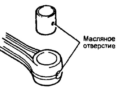
(2S, 2S-T) Install the bushing on the special tool, fixing it with a ball in the oil (lubricant) bushing holes.
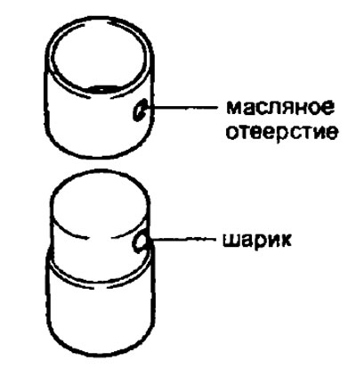
Align the lubrication holes of the bushing and connecting rod.
Using a special tool and a press, press in the bushing.
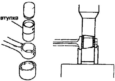
- V) Measure the piston pin oil clearance and, if necessary, grind or re-grind a new bushing until the nominal clearance is obtained.
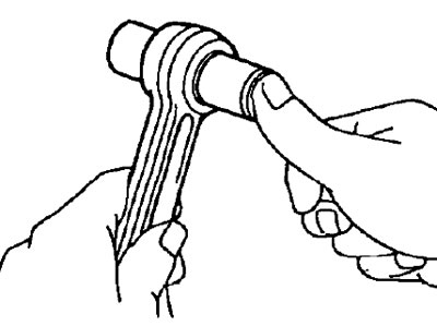
- G) Check piston pin operation at normal room temperature. Coat the piston pin with engine oil and push it in as shown.
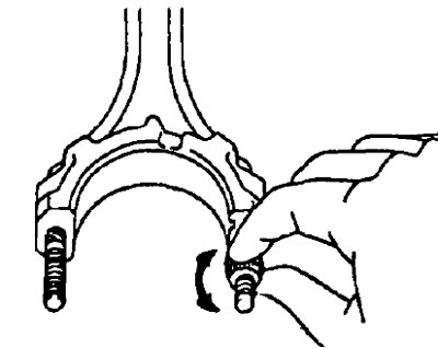
G. (3S-FE, 4S-FE, 4A-FE) Check connecting rod bolts.
- A) Thread a nut onto each bolt and make sure the nut can be easily turned by hand over the full thread length of the bolt.
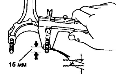
- b) If the nut cannot be screwed on by hand, measure the outside diameter of the bolt thread with a caliper in the area where the threads are most worn.
- Standard diameter:
- 3S-FE, 4S-FE - 7.860-8.000 mm
- 4A-FE - 8.860-9.000 mm
- Minimum Diameter:
- 3S-FE, 4S-FE - 7.60mm
- 4A-FE - 8.60 mm
Note: If such a zone is difficult to detect visually, then measure at a distance of 15 mm from the end of the bolt, as shown in the figure.
If the outer diameter of the thread is less than the minimum, replace the connecting rod bolt and nut as a single assembly.
D.(7A-FE) Measure the outer diameter of the bolt with a caliper in the area of greatest wear. If such a zone is difficult to detect visually, then measure at a distance of 20 mm from the bolt head, as shown in the figure.
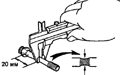
- Bolt outer diameter:
- nominal - 8,860-9,000 mm
- Minimum - 8,600 mm
If the diameter is less than acceptable, replace the bolt.